Blog
12 Machines of Christmas
Beginning on December 12th!
12 Machines of Christmas
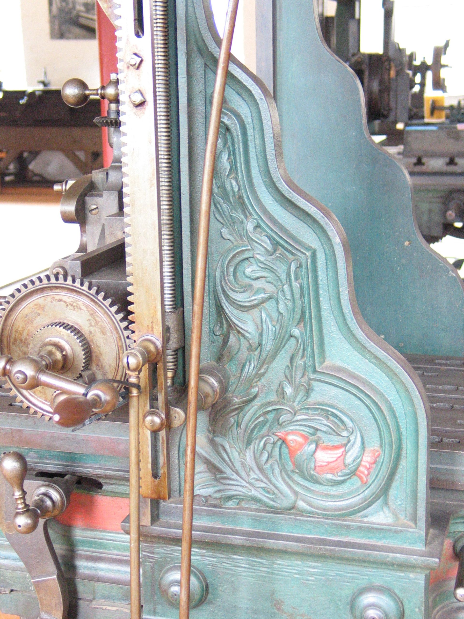
Metal Planer
Made by Putnam Machine Co., c. 1845
Fitchburg, Mass.

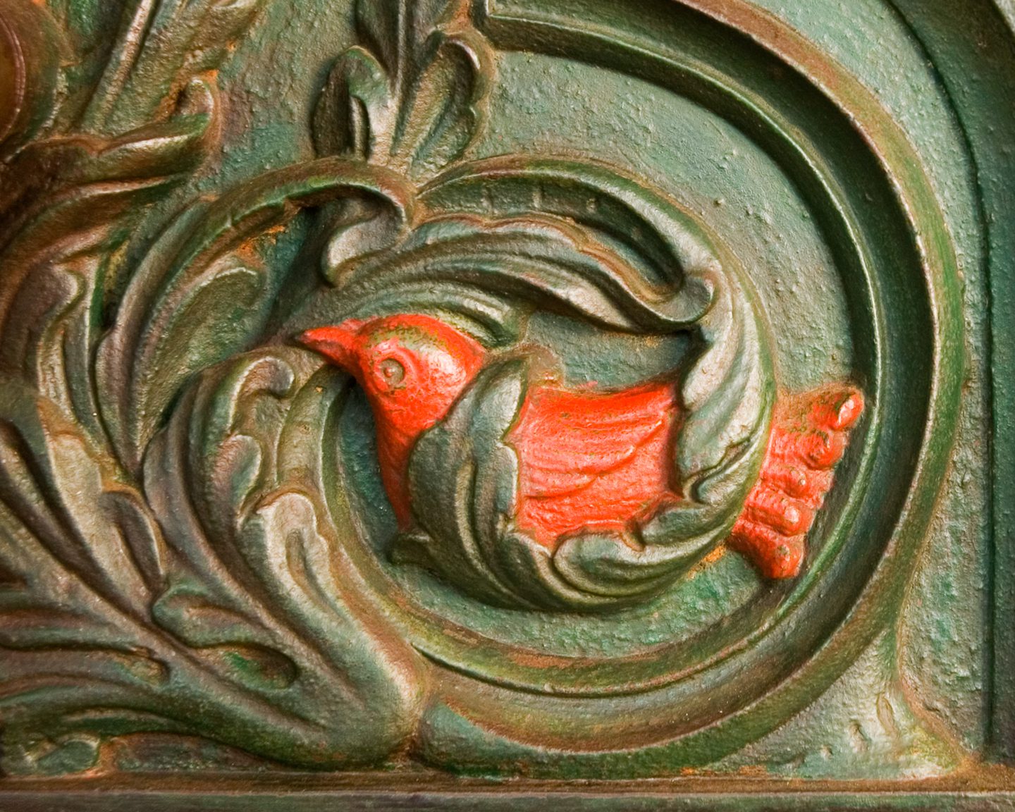
Planer, painted green and red. Scallop shell casting on top of bridge, bird in vine on side. Cast in bridge: Putnam Machine Co., Fitchburg, Mass.
When we take visitors through the museum, we compare this planer to one from twenty years earlier that has no detail, no paint, and cylindrical handles rather than the ergonomic ones found here. Between 1825 and 1845, machine companies like Putnam added detail to increase machine competitiveness.
Gift Of: Chester B. Chappel
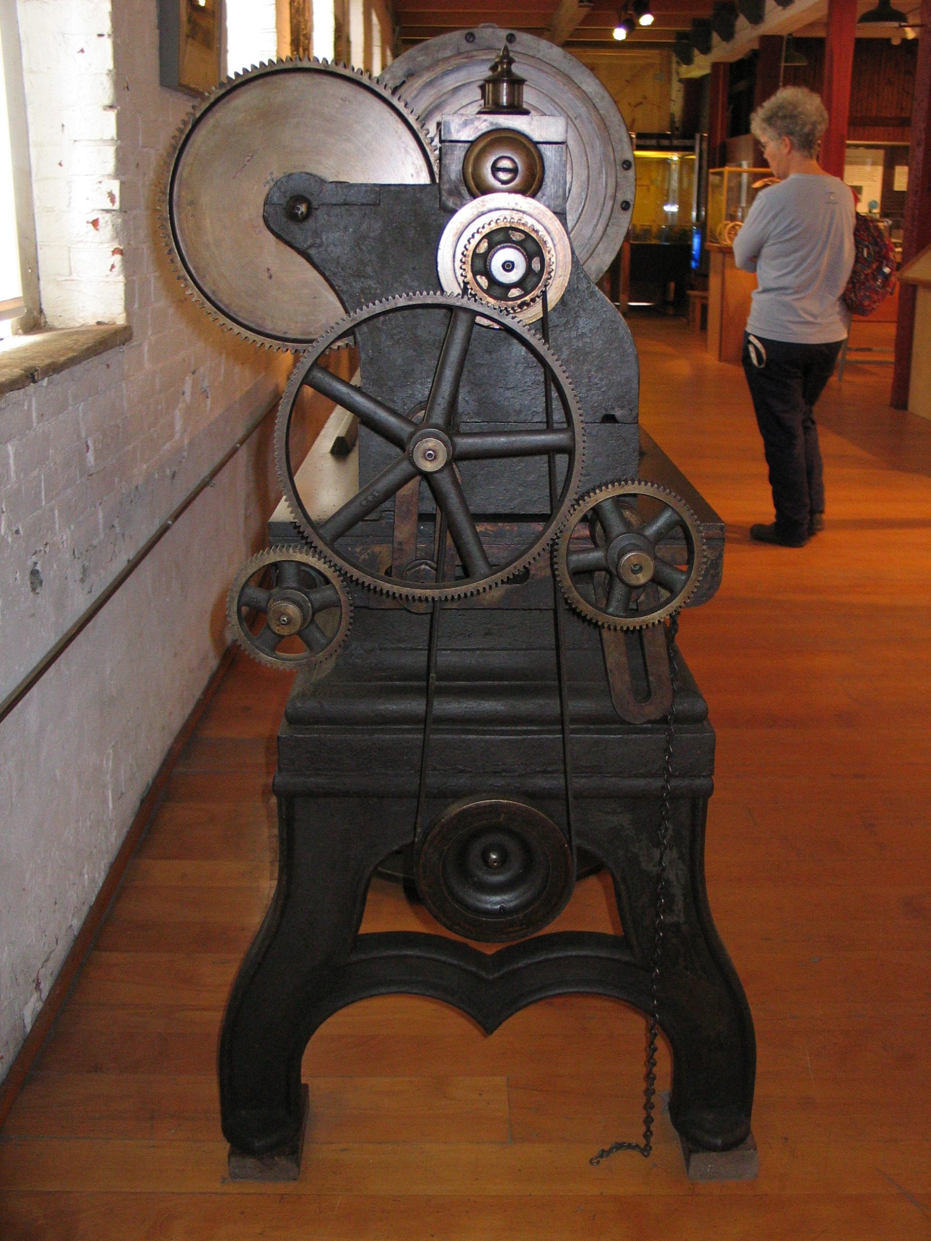
Vertical Metal Shaper
Made by Warner & Whitney, 1872
Nashua, NH

This machine is also described as a slotting & paring machine. Shaping, slotting and planing are done with reciprocating motion. Milling is almost always done with the cutter rotating. (The “almost always” is invoked on machines like a “vertical lathe” that’s also called a “vertical boring mill”.)
There are things that a slotter can do that a mill can’t. A mill can’t cut an internal square-bottomed slot (like the internal keyway in the gear that’s on display on this machine’s table) or cut internal teeth on a gear.
Ed Battison wrote in the Fall 1977 Tools & Technology report, “The Nashua directory for 1866 describes Warner & Whitney as manufacturers of all kinds of machinists tools, steam hammers, sugar mills, and shafting. This machine was made in the 1860s, but very likely of earlier design. …This slotting and paring machine, about eight feet tall, is built around an integral iron column that is fluted as nicely as if it were for use on the façade of some distinguished building. Establishing a precise date when the design might have originated is difficult. The maximum cutting stroke is about 12 inches and the crank is driven by a double set of gears and a time-saving Whitworth ‘quick-return’ motion. This quick-return feature required extra power and added considerable expense to the total selling price.”
Gift of Botwinik Brothers
Back in November, we profiled the centerless grinder pioneered by Lewis R. Heim. Compare that to these grinders:
Pedestal-Type Grinder
James L. Lord, patented Aug. 15, 1854
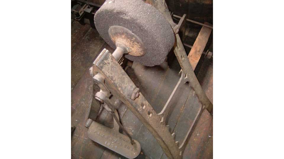
Grinding has always been a means of forming a hard material. Very long ago, this would have been a matter of rubbing a hard, gritty stone against the object that was being shaped. As humans’ use of various materials evolved, the grindstone became something that was rotated against other materials. And currently, a grindstone may be synthetic and not even have begun life as a stone.
One of the ways machines were commonly powered in the 1800s was “pedal power.” That would cause the wheel to spin, which would grind the surface of the workpiece. This pedal-driven grinder was patented in 1854 and was probably intended especially for farmers. Their tools, such as scythes and butcher knives, needed constant sharpening. The pedal grinder maintained sharp edges.
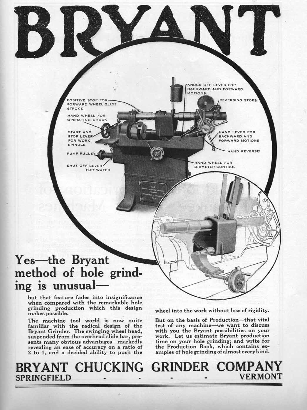
Cylindrical Grinder
Bryant Chucking Grinder Company, 1909
Springfield, VT
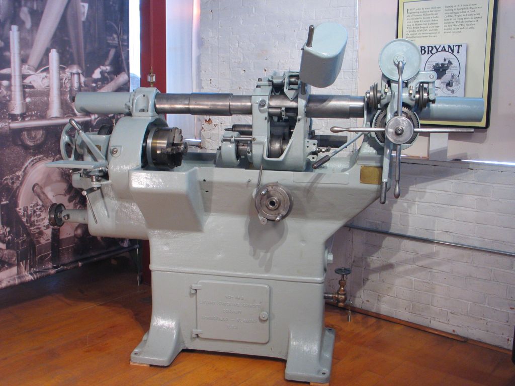
Starting in 1910, William L. Bryant was sold grinders to Ford, Cadillac, Wright, and many other firms in the young auto and aircraft industries. With the outbreak of the First World War, the Bryant plant doubled in size and ran shifts around the clock.
With the coming of the internal combustion engine, Bryant’s grinder created precise cylindrical surfaces, each with its ends at a true right angle.
Surface grinding or grinding, in general, is an important manufacturing process. This process produces exceptionally close tolerance features along with a very high surface finish in mostly hardened materials. The manufacturing of cutters rely on grinding to produce the cutting-edges.
Gift of: Bryant Grinder Corporation
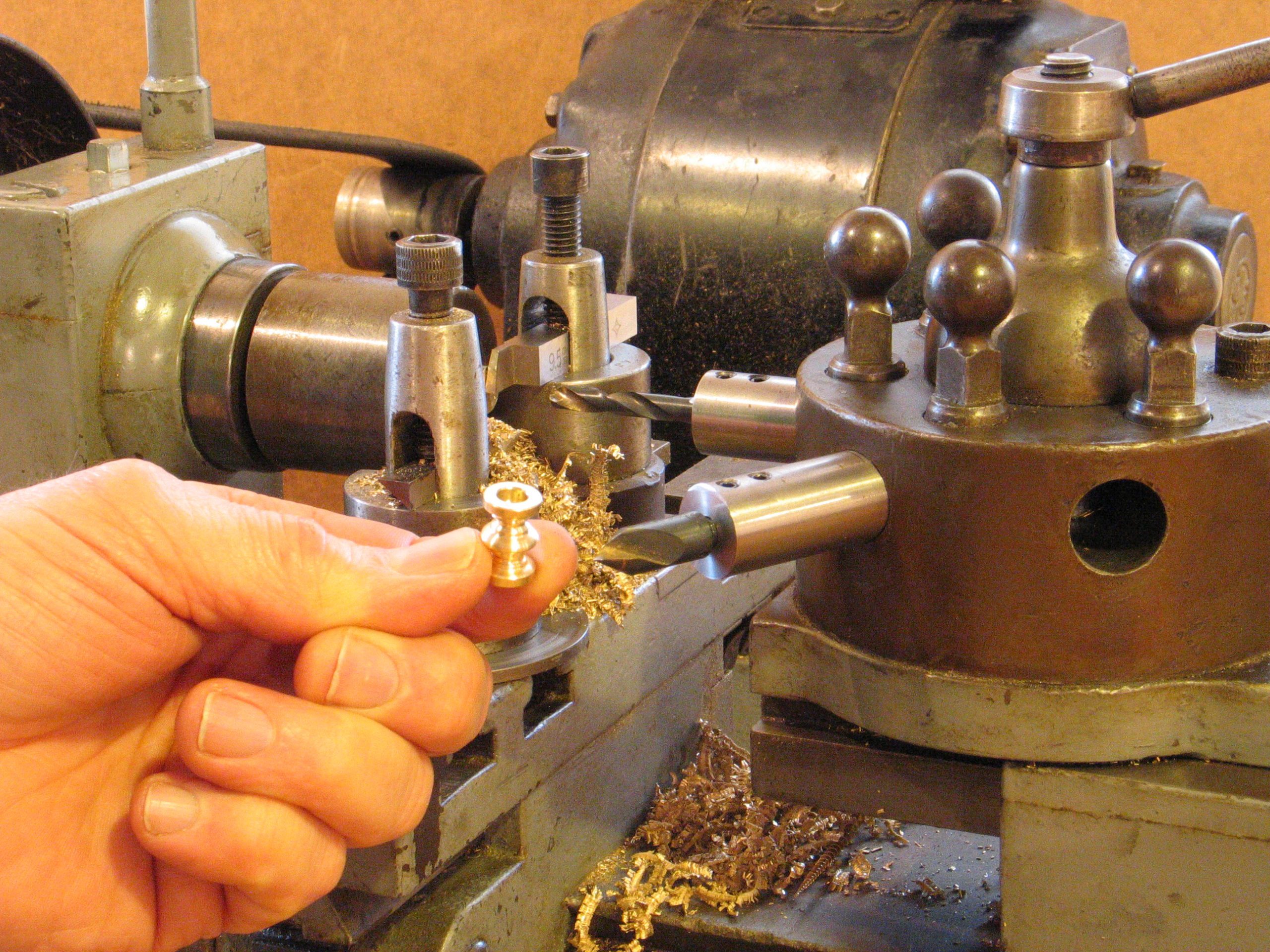
The museum has 4 turret lathes currently on display (one is in the Innovation Station and is operational during summer season.)
Why is it called a turret lathe?
Originally, the designers called this a “screw milling machine.”
During the Civil War, new ironclad warships were topped with powerful gun turrets. Revolving tool post lathes soon became known as turret lathes.
Who invented the turret lathe?
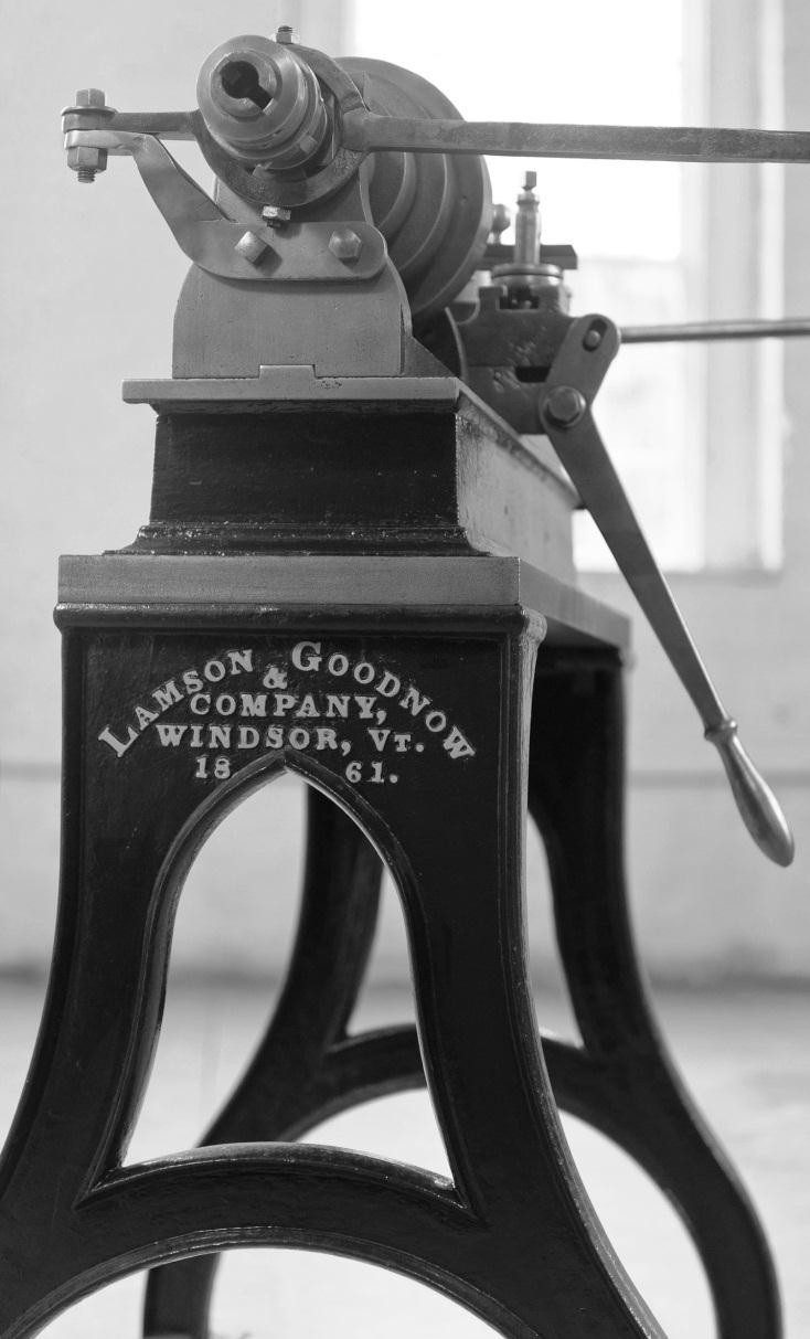
Early turret lathes were already being used at the Silver and Gay shop in Massachusetts when Frederick Howe was an apprentice there in the early 1840s. (That company went through several changes of name. Ken Cope’s book on lathes says that it didn’t become “Silver, Gay & Co.” until 1857. In Howe’s time it was Gay, Silver & Co.) About that time, E. K. Root was also working on a revolving lathe at the Colt Armory in Hartford, Connecticut. In 1847, Howe brought the idea to Windsor, where he, Richard Lawrence, and Henry Stone developed an improved version. And the development is remarkably complete! Our 1861 machine, apparently the oldest of its kind in the world, is almost completely similar to the 1911 example or to the Silent Salesman.
What does it do?
The turret lathe increased productivity by speeding up the making of screws and other complex shapes.
To perform a series of operations on a single workpiece, the machinist may need several different cutting tools. A lathe with a revolving tool post allows the machinist to rotate a new cutting tool into position without moving the workpiece and without taking time to install a new tool for each type of cut.
Turret Lathe
Lamson, Goodnow & Company, Windsor, Vermont
1861
Flat Turret Lathe
Designed by James Hartness
Jones & Lamson Machine Company, Springfield, Vermont, 1896
Of the first 100 J&L flat turret lathes built, 13 went to other machine tool companies, 12 to locomotive works, and 10 to auto makers. They were also used by companies building industrial products ranging from farm machinery to elevators. In the early twentieth century, the flat turret lathe became an important tool in the rapidly growing auto industry. Check out this article from American Machinist May 6, 1891.
The flat turret lathe has a broad circular revolving plate that holds the tools. The width of that plate contributes to the tool’s rigidity. The central part of the plate is clear, so that on long cuts the workpiece can pass completely over the turret allowing for a longer cut.
Gift of North American Rockwell
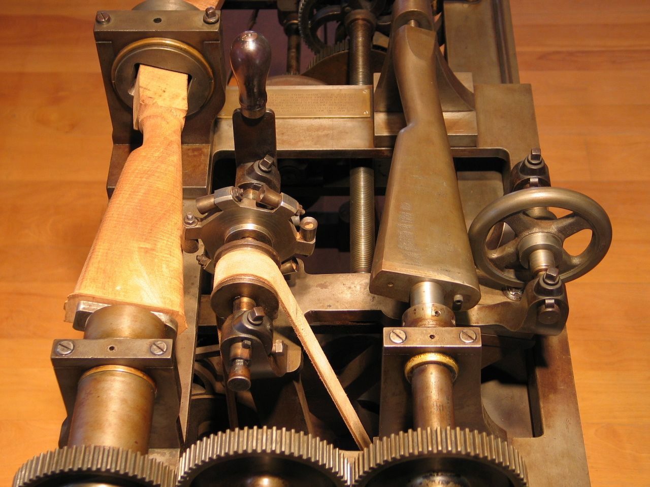
Gunstock Lathe
Ames Manufacturing Company, 1857
Chicopee, Massachusetts
In 1819, Thomas Blanchard invented a copying lathe that could create the complex shape of a gunstock. By duplicating that shape over and over, the lathe dramatically reduced the time and labor needed to make gunstocks. The machine displayed here is a later version, designed by Cyrus Buckland at the Springfield Armory in the 1840s. Buckland also developed machines for shaping other parts of the gunstock. This particular lathe went to England along with Robbins & Lawrence machines sent to outfit the Enfield Armory. It worked there for perhaps a hundred years before being given to the U.S. Park Service.
How does it work?
Early lathes could make only simple shapes, such as wheel spokes and chair spindles. The gunstock lathe copies the irregular shape of a three dimensional iron pattern.
This tracing lathe has two wheels, the same size and shape as each other. As one wheel moves over the shape of the gunstock pattern, a second rotating wheel—containing sharp cutting tools—duplicates the motion of the first wheel, re-creating the shape of the pattern, and producing gunstocks that are all alike.
On loan from the Springfield Armory National Historic Site
Milling Machine, Serial No. 1
Bridgeport Pattern & Model Works, 1938
Bridgeport, Connecticut
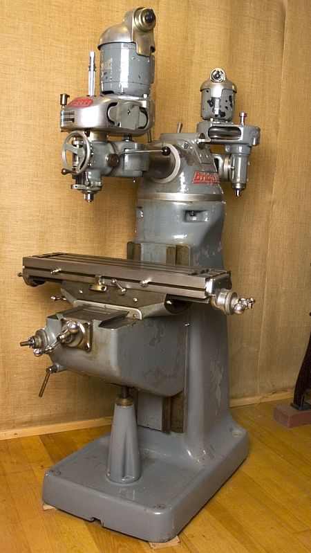
After its introduction in 1938, the Bridgeport mill became a machine tool icon—imitated and used around the world. As with other milling machines, the table that holds the workpiece moves under the spinning cutting tool. In the Bridgeport-style milling machine, the spindle that holds the cutting tool can be aligned in different positions. This adjustability and ease-of-use made the Bridgeport-style machine the most widely-used and popular milling machine of the twentieth century.
Color edition Bridgeports tested for CMTS (now IMTS), 1970
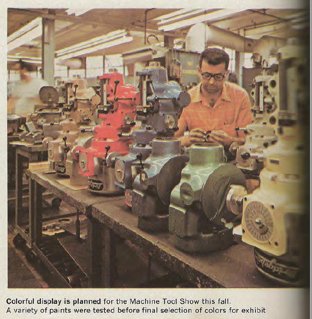
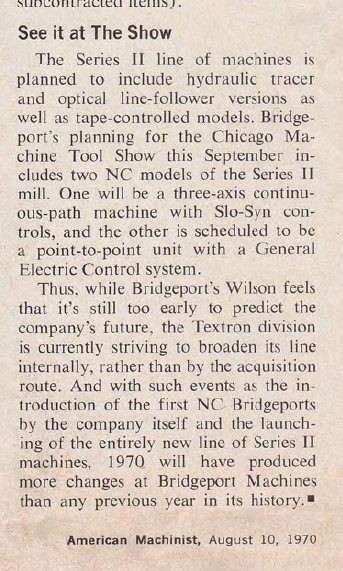
This article from American Machinist, August 1970, “How They Build the Bridgeport” is a great snapshot in time, of an iconic company near its peak.
Gift of Bridgeport Machine, Division of Textron
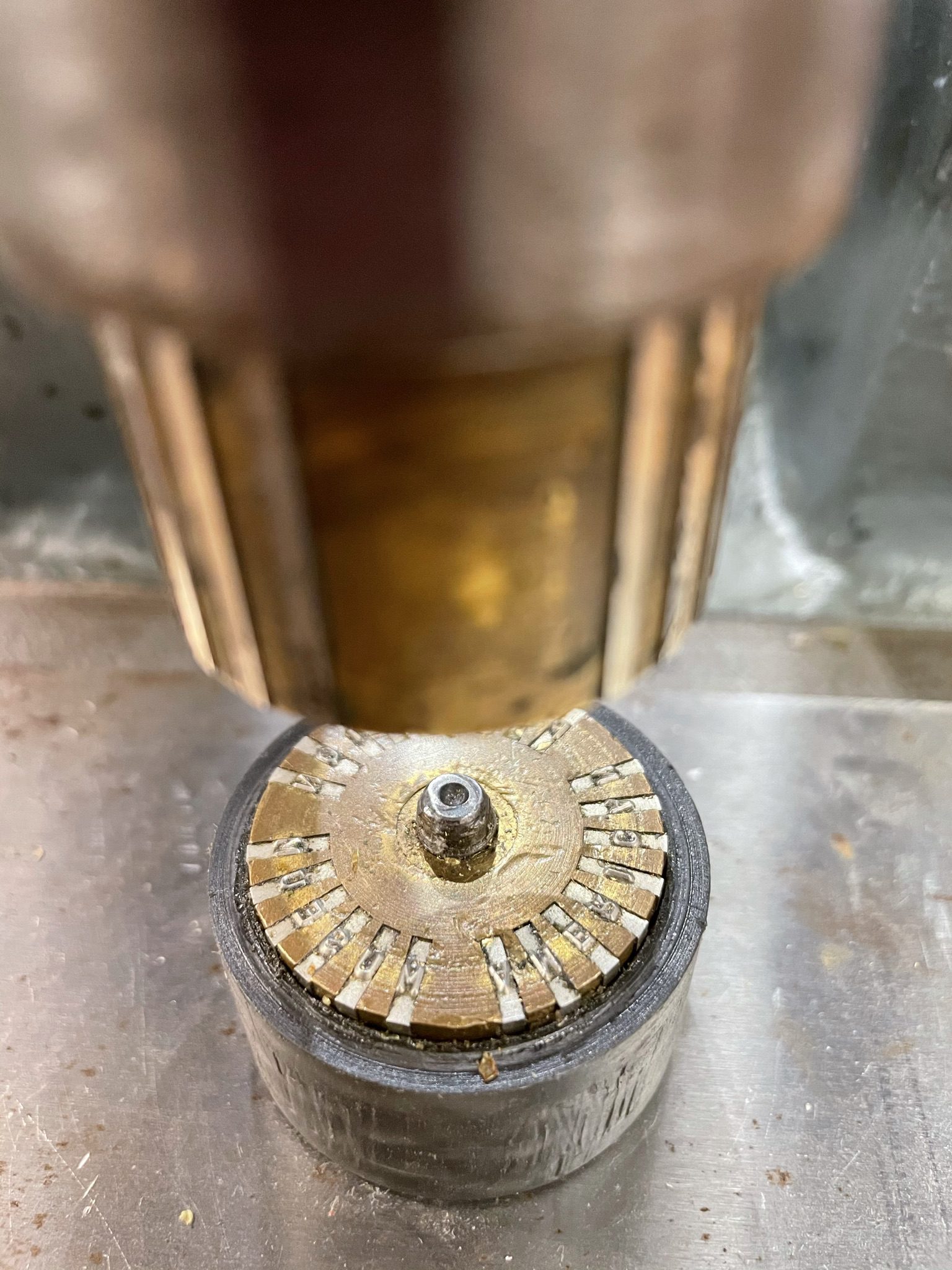
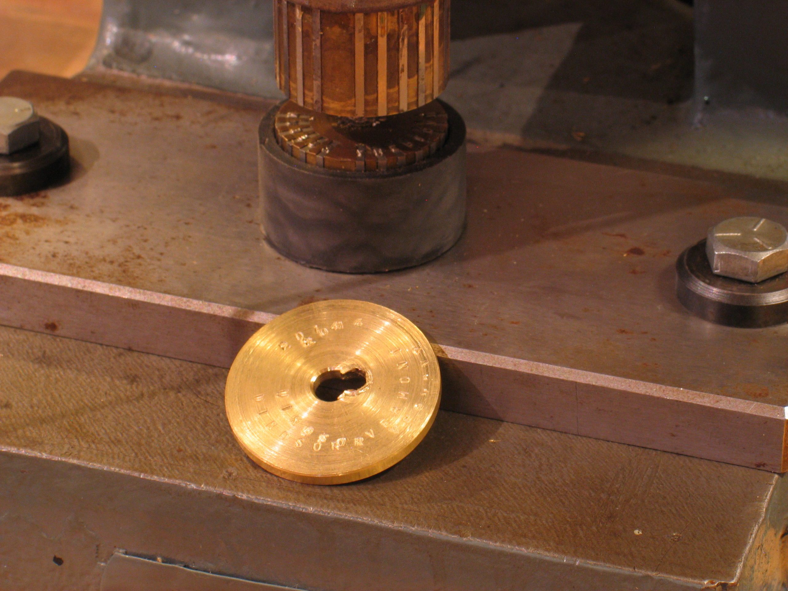
Stamping Press
Automatic Machine Co, c 1920-1950
Bridgeport, CT

This machine doesn’t remove or add material. The Stamping Press uses kinetic energy stored in the flywheel to stamp designs onto metal. The motor spins a flywheel which stores energy (inertia), which is released when the lever is pulled, transferring the rotating force straight down into the stamp. It is called a 1 ton press because that’s the amount of force that the ram strikes downward with.
Our working machine is located in the Innovation Station and we stamp brass gears with the year and “American Precision Museum, Windsor, VT.” Often, today’s manufacturers use laser etching rather than stamps.
Gift of Alden Sherman
Drill Press
Unknown Maker, c 1863
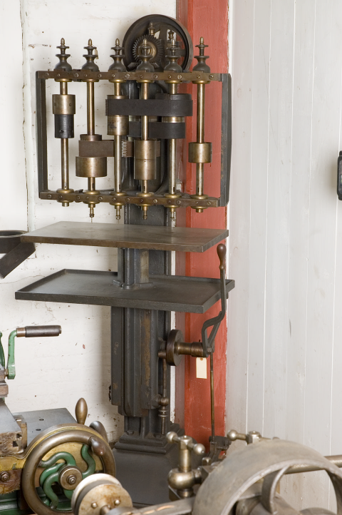
With this six-spindle drill press, the operator can drill up to six holes of different diameters, in rapid sequence, without having to stop and change drill bits. When the operator steps on the foot pedal, the table rises, pushing the workpiece up into the spinning drill.
Around that era, a new technique was the use of jigs. In this case, a jig would have hardened parts with holes through which the drills could project into the workpiece that was securely clamped inside. Some research indicates that this is a copy of a Robbins & Lawrence machine (by an unknown maker).
(Gift of Albert I Prince Technical School)
That was then….
Inletting Machine
Ames Manufacturing Co, 1855
Chicopee, MA

This machine made by Ames used a combination of pattern-tracing and multiple spindles (with different tools on each) to create the pocket that a rifle’s lockplate would fit in. The belt on the machine could be shifted to an index position while the operator changed the tool.
Gift of: US Repeating Arms Company
and this is now:
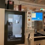
3 Axis CNC Milling Machine, DT-1 Vertical Machining Center HAAS Automation Inc, Oxnard, CA
with Automatic Pallet Changer, Midaco Corporation, Elk Grove Village, IL
and
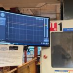
CNC Machine Condition Monitoring System, D-Tect-IT Caron Engineering, Wells, Maine
This machining center has the capacity for up to 20 tools, plus one in the spindle. A double-arm gripper swaps tools automatically to minimize non-cutting time. One of the tools is a probe (with a ruby tip) that checks the position of the parts. The combination of improvements on this machine means higher quality pieces holding accuracies 10x thinner than a human hair, improved productivity (100 times greater than 50 years ago), and greatly increased safety for operators. This machine incorporates multiple operations represented throughout he museum in individual machines.
Gift of: Haas Automation, Midaco Corporation, and Caron Engineering
Mechanical Press
Made by Parker Bros, 1870
Meriden, Conn.
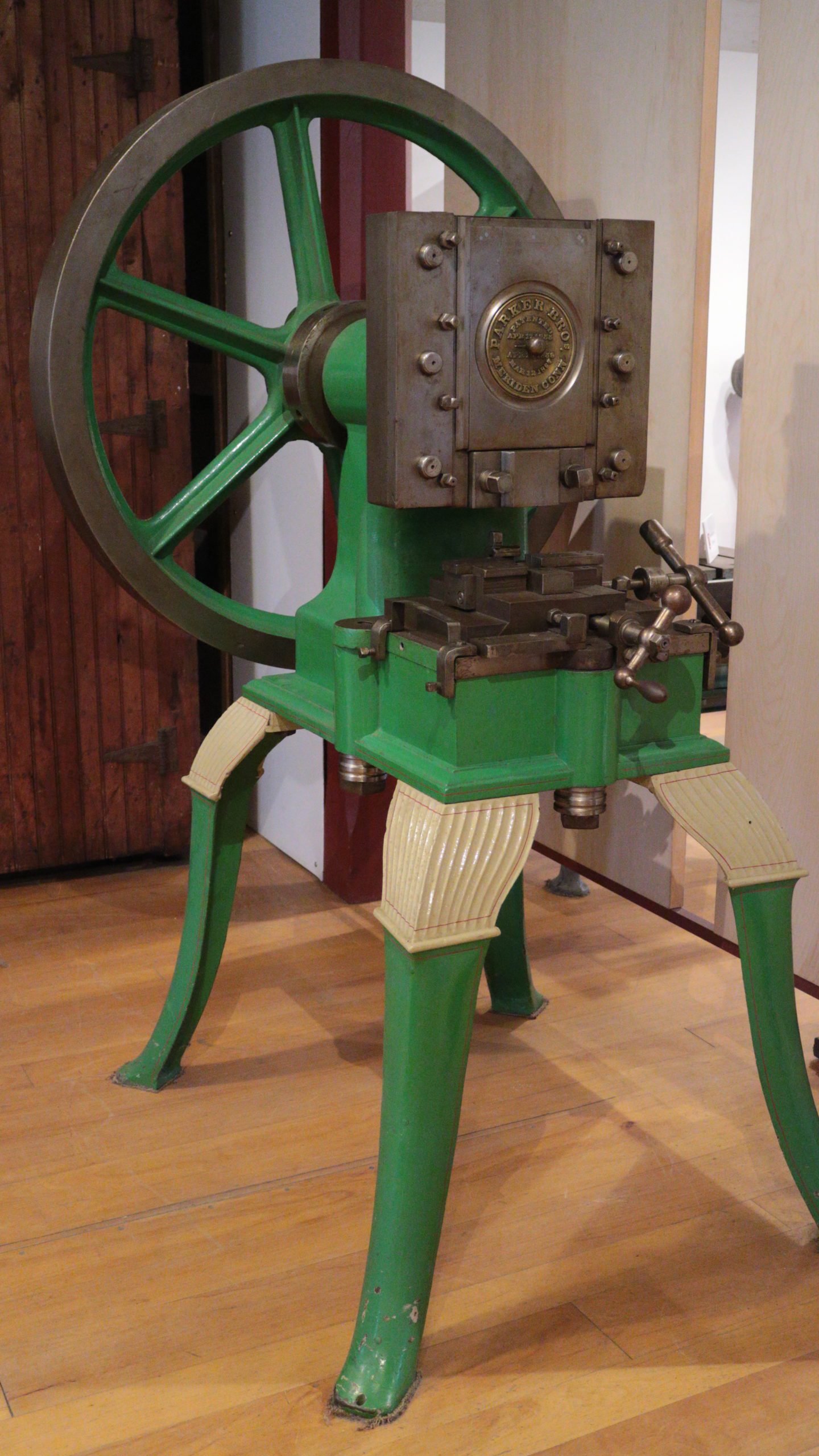
Patented Apr. 17, 1855, and Mar. 12, 1867.
It can stamp, like the mechanical press in our working machine shop. It can also form the workpiece in other ways, like pressing metal to make a cup or simply bending a strip. It can cut a strip to length (shearing). It can pierce (punching). All that’s needed is to change the tooling.
The wheel is 41″ in diameter and weighs about 500 pounds. The rest of the machine weighs about 1200 pounds.
Gift Of: John V. C. McKinney
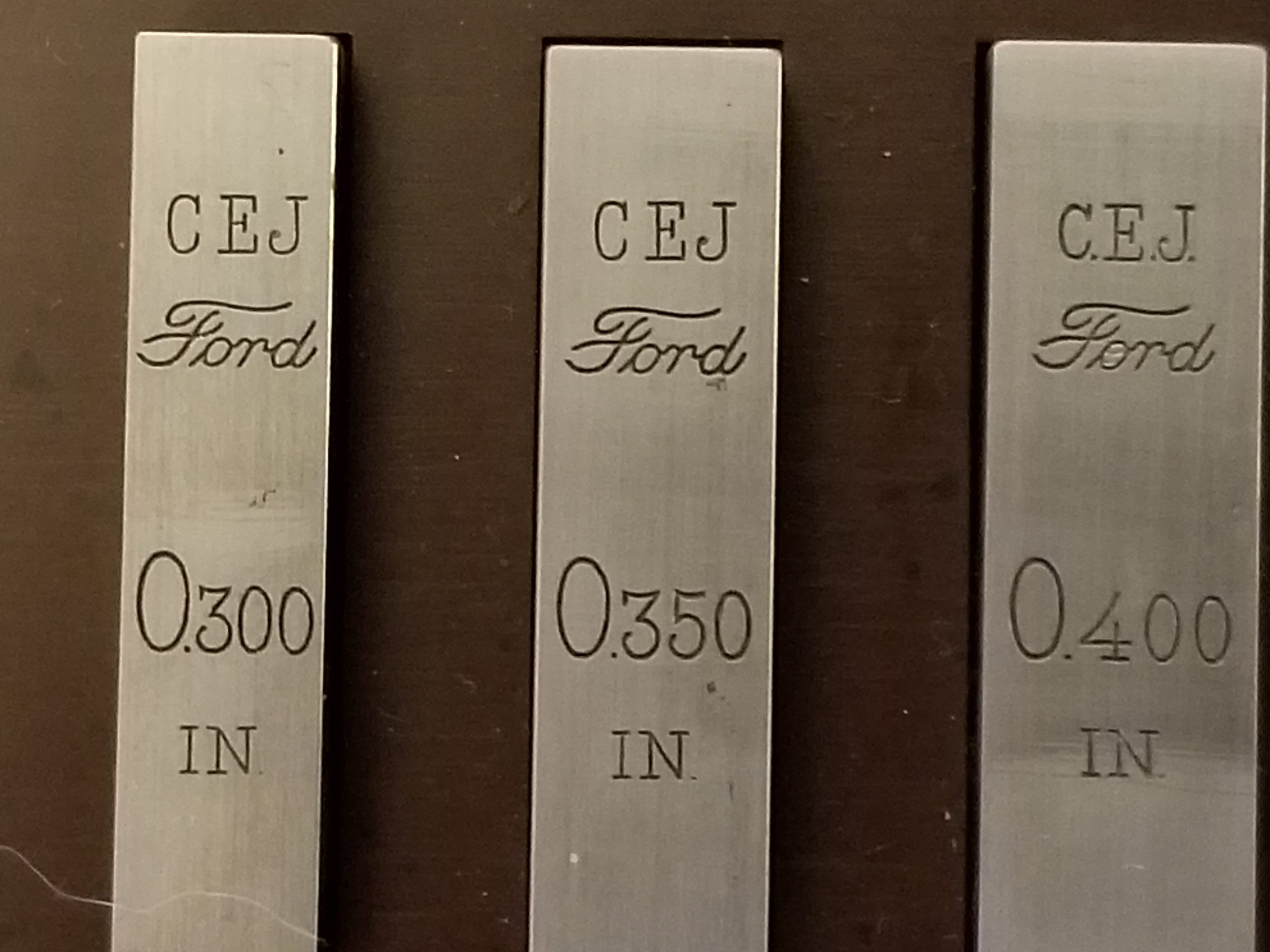
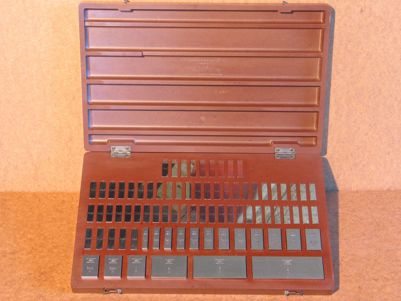
Gage Blocks
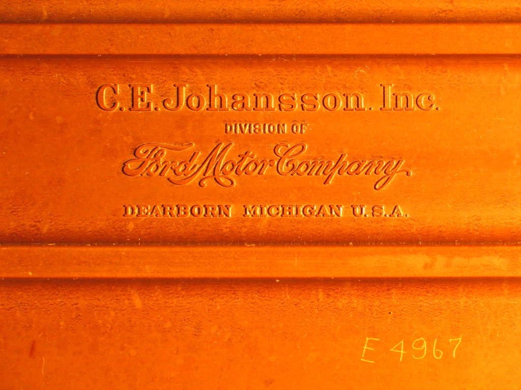
C.E. Johansson Inc, Division of Ford Motor Co, 1923
Dearborn, MI
For more images
Before Jo-Blocks, most manufacturers used templates, or custom gages for the parts that they needed. Carl E. Johansson of Sweden produced the first modern gage (or ‘gauge’) blocks in 1896. He was excited to tour the Mauser-Werke in Germany and found that there was no actual system, but that gage blocks had been made and stored in thousands.
“When C. E. Johansson found…the quantity of gage blocks that would have to be produced before the new manufacture of the Mauser rifle could get going at Eskilstuna, he conceived the idea that a relatively small number of gage blocks might possibly be made so that in combination with each other they would provide all the measurement figures required in the fabrication of rifles. And thus there was conceived….the combination gage block set.” -from C. E. Johansson 1864-1943, The Master of Measurement, by Torsten K. W. Althin at the request of AB C. E. Johansson.
Eventually, Henry Ford bought the C. E. Johansson company for use for Ford production. “What Mr. Johansson wants, that must he get,” Ford is reported to have said. In this case, what he wanted was a temperature-controlled environment, which not event the International Bureau of Standards in Paris had at the time. Metal tends to shrink in the cold, which means that there would always be variability based on the temperature of the environment or even variations in the material. Eventually, Johansson did get his temperature-controlled room at Ford.
These blocks are so finely finished that when they are placed across each other and twisted into parallel (called “wringing”), their faces stick to each other.
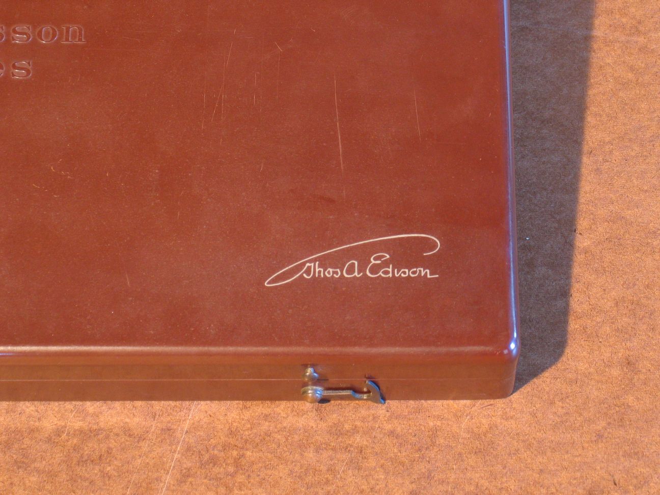
Henry Ford gave this particular set in the Bakelite box to Edison, whom he greatly admired. Note the stylized signature “Thos. A. Edison” inlaid in the top of the lid. This set was never used in any shop setting; its surfaces are still perfect. Apparently the gift to Edison was made early after the purchase of the Johansson company; the serial number on the blocks is 27.

Gift of the Charles Edison Fund, Inc
These two lathes accommodate long stock, and large diameter work. Interestingly, each of these has had riser blocks put in under the headstock so that they could handle larger diameter pieces.
Granite Engine Lathe, 175″ Long
Made around 1825, probably by Crown & Eagle Mills
N. Uxbridge, Mass
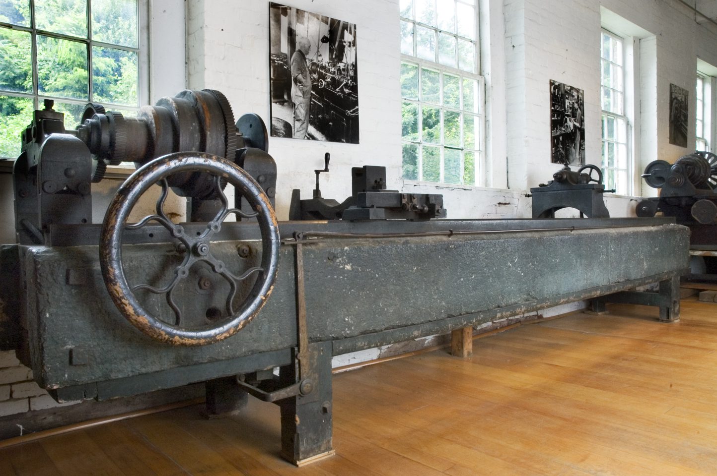
This machine is from the Crown and Eagle Mills in N. Uxbridge, Mass. Used in making and maintaining the equipment there.
The left and right parts of the headstock are independent. The feed mechanism was updated and is a reversible chain-drive. An on/off and reverse switch is a long bar that goes along the front of the lathe – so the operator can reach the bar from anywhere on the front.
Originally wood bed, replaced with granite for stiffness and weight. The weight and rigidity allow the lathe to handle a difficult piece where the weight of the workpiece is eccentric, for instance.
This machine uses the features of David Wilkinson’s patent of 1798: a three-point bearing system for tool slides and a weight to hold the slide against the ways without any slack.
Engine Lathe, 248″ Long
Made by Windsor Manufacturing Co, 1867
This engine lathe was made here (in the Armory building). The owners of this place used it in Shelburne Falls, Mass., where they had another plant. When it was retired, it came back here. It shares some of the features of the #6, but it’s much more sophisticated and accurate. The heavy carriage actually grips the ways, while the #6 relies on weight alone. #12 can cut threads, #6 must use a threading die to do that.
Gift Of: Lamson and Goodnow
stay up to date
Want more content from the American Precision Museum?
Sign up to receive news straight to your inbox!
By submitting this form, you are consenting to receive marketing emails from: . You can revoke your consent to receive emails at any time by using the SafeUnsubscribe® link, found at the bottom of every email. Emails are serviced by Constant Contact