Blog
Machine of the Month: The Robertson Milling Machine

By John Alexander, Collections Technician
jalexander@americanprecision.org
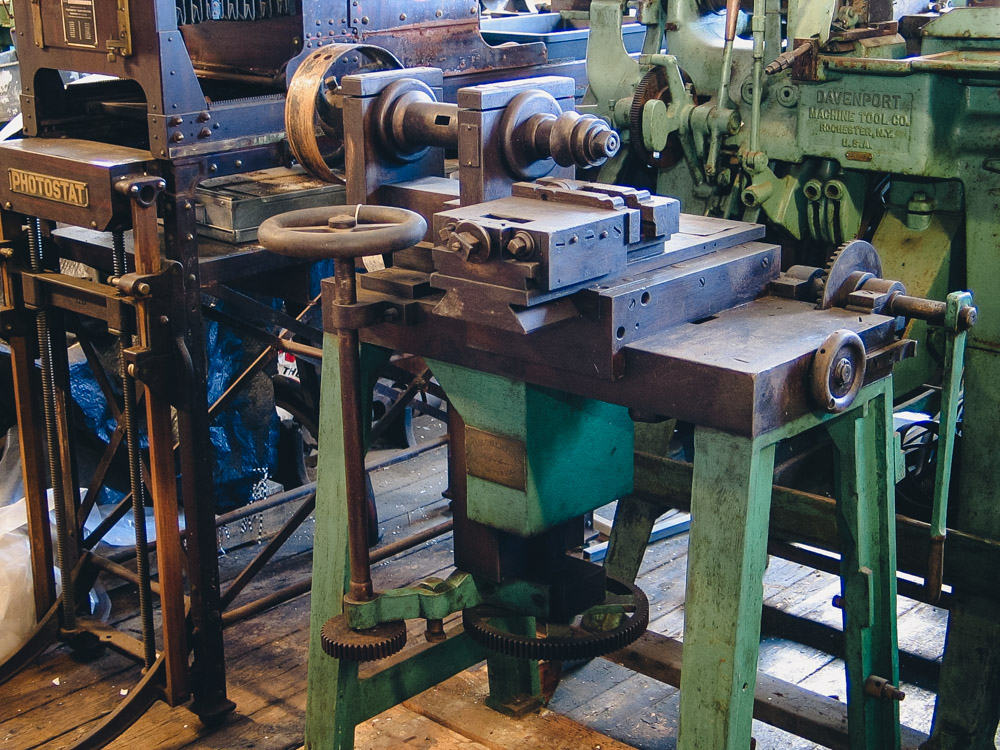
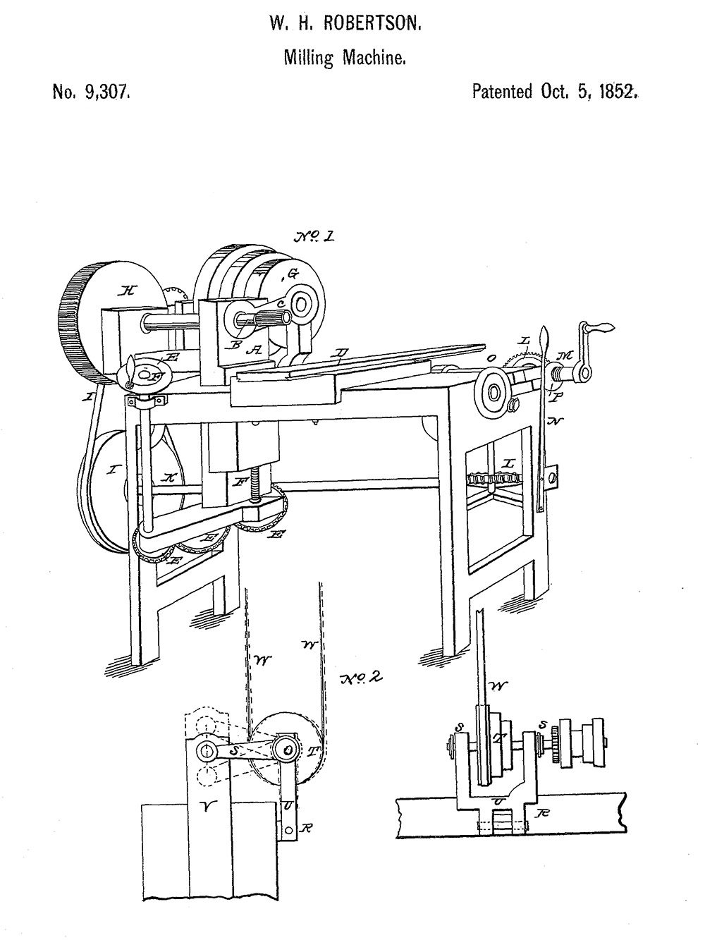
This was built in 1852 or 1853 using the first American patent for a milling machine. I liked the idea that this machine had gotten the first milling machine patent. I printed out the patent from Google, and I was disappointed. The patent has to do with maintaining belt tension as the headstock is moved up and down. Not a revolution in milling machines.
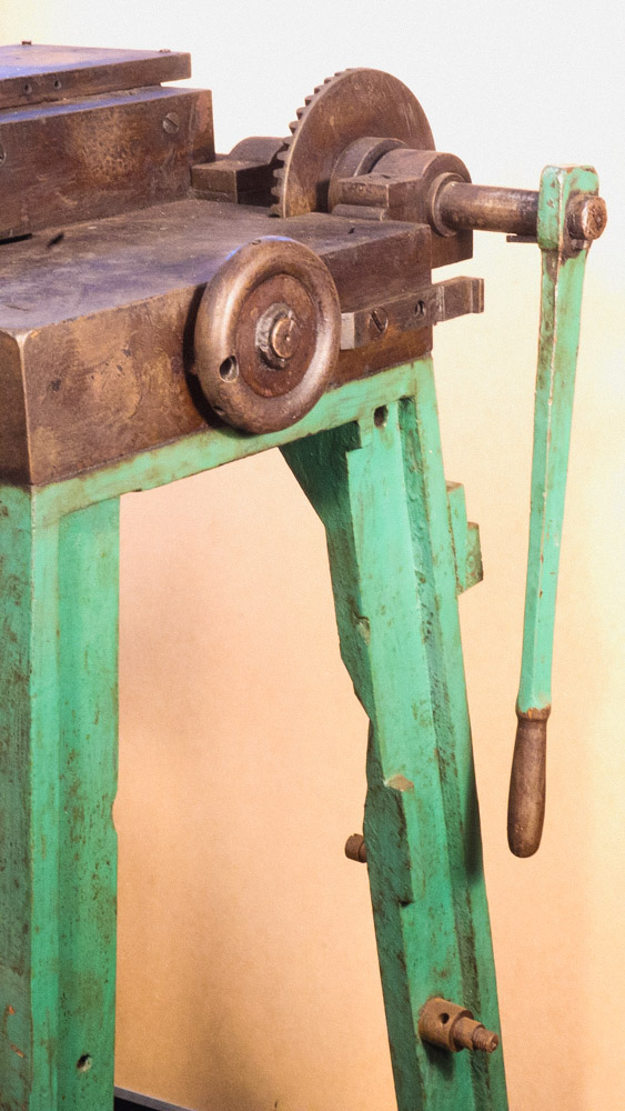
It’s an attractive machine that had interesting solutions for some of the problems of its time. The headstock is mounted on a large piece of iron (3 ¼ inches left-to-right x 7 inches front-to-back and 18 inches under the headstock) that is moved up and down by turning a crank. The crank is on the upper end of a rod with a gear at the other end. It turned two more gears, which turned a threaded rod, which moved the headstock vertically.
The middle gear is missing from the gear train of three at the bottom, so we aren’t able to move the headstock or most other parts as they were intended to move in the beginning. There’s also a layer of anti-rust stuff on the unpainted surfaces (dried goo), which would have to be removed to free up the parts.
The Robertson mill is adjustable fairly quickly, but unfortunately, the Robertson is less rigid, at least in some ways. That means the machine can’t take such a deep cut or expect a good finish in stressful situations. Mr. Robertson was certainly concerned with rigidity. Why else would the machine have such heavy, stiff components? For instance, the table is a piece of cast iron 3 inches thick! The headstock rises and descends on a beam 3 1/4 inches wide x 7 inches front-to-back and 18 inches tall.
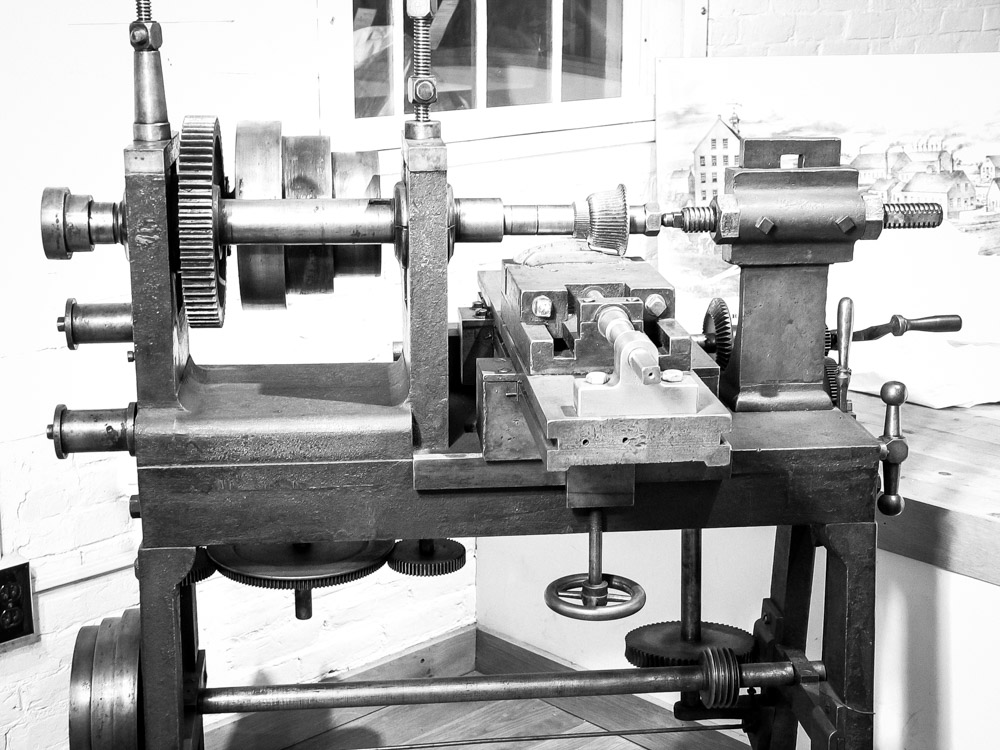 The Howe milling machine was developed here at Robbins, Kendall & Lawrence (circa 1848). It promptly evolved into the Lincoln mill (circa 1854). They were relatively rigid, making for strong cuts and good finishes. Perhaps their greatest problem was that they were slow and clumsy to change the height of the tool over the workpiece. Since the workpiece passes under the whirling cutter, that height determines the thickness of the finished work. This shouldn’t be a problem if you have been working on the same product for a long time. But if there were frequent changes, the time that was lost in adjusting, along with the frustration, would add up. Read More about Howe’s Milling Machine
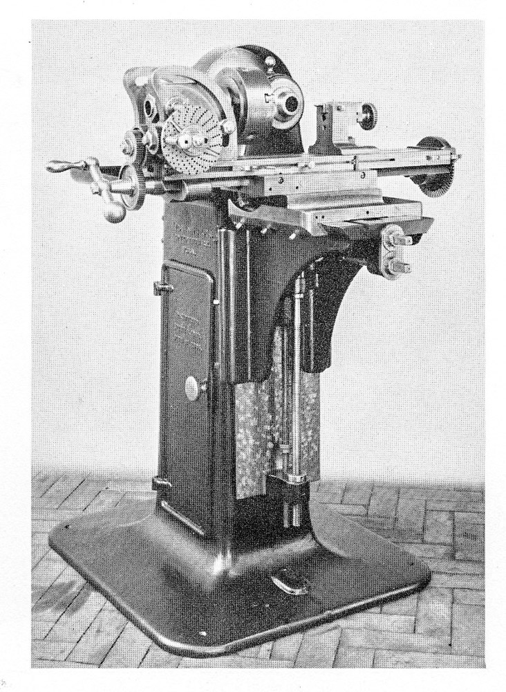 Not too much later, “knee” type machines such as the Brown & Sharpe universal mill (1862) would combine rigidity with adjustability quite well. This improvement was made by using dovetail ways to support the slides. Dovetails are still a very important feature on most machine tools. Read More about the Brown & Sharpe Mill
What might be lacking in Robertson’s design?
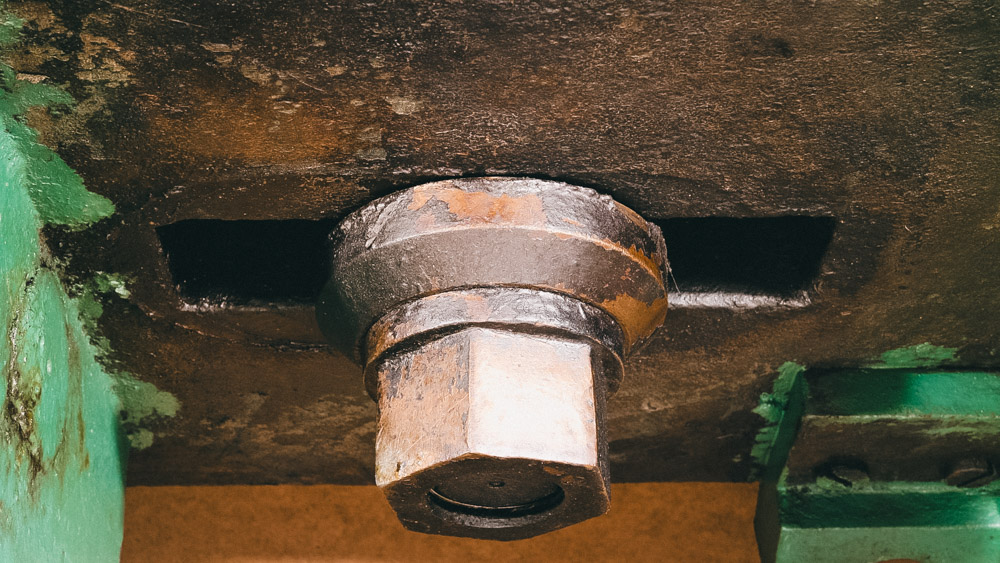
Most of its basic component parts fit the description of “massive,” and many parts are “very stiff.” On the other hand, it appears that the headstock’s rising and falling and the slide that locates the workpiece to the right and left are each held only by one very large stud. (Studs have threads on both ends.) The threads are 1 1/2 inches in diameter, and the nuts on the threads are 2 1/8 inches across the flats.
The headstock moves vertically in a thick channel of cast iron. (The nameplate is attached to one side of it). If the headstock’s slide were precisely fitted to the trough that it moves in, that would be good. But it’s probably not fitted very precisely, at least by modern standards.
An important thing about the good later designs was that many included some mechanism for adjusting the amount of slack for the sliding surfaces. (An adjustment to achieve precision.) Those designs include screws that can be tightened on those machines that will take up the side-to-side looseness for a slide. It appears that the Robertson machine has that in only one place.
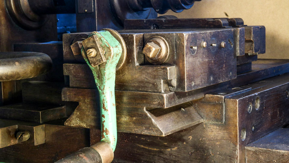
The slide just under the vise moves in an adjustable dovetail on the bottom. The adjustment enables it to be tightened to compensate for wear. On the later machines, all the slides have adjustable dovetails.
If you want less vibration from the wiggling of the headstock on this machine or the base of the work-holding slide, the one option on the Robertson is tightening the big nuts. One could put a lot of pressure on by tightening with a long-handled wrench, but that wouldn’t keep the assemblies from the very small amount of pivoting that would cause problems of one kind or another.
A single bolt in the middle of any span just isn’t enough to keep it from twisting. One bolt toward each end (even if they aren’t very large in diameter) will anchor it much more firmly. When well-fitted dovetails are tightened down carefully, they have continuous contact along their length and don’t allow wiggling. Yet, the slide can move freely with only modest friction in making its appointed journey.
Most of this machine’s parts from the speed-changing mechanism for the spindle and the workpiece were given some other task sometime in the last 170 years. Or, to speak plainly, those pieces are gone.
There’s no longer any way of changing the cutter’s speed on our machine. In the patent drawing, the stepped pulley behind the headstock’s spindle would have been driven by another stepped pulley that was part of a countershaft overhead. The three steps of the pulley feeding the three steps below would have offered three rotational speeds to the spinning cutter and feed system. The countershaft would usually provide something like the neutral gear in a modern car. That “neutral” position would act as the machine’s OFF / ON switch.
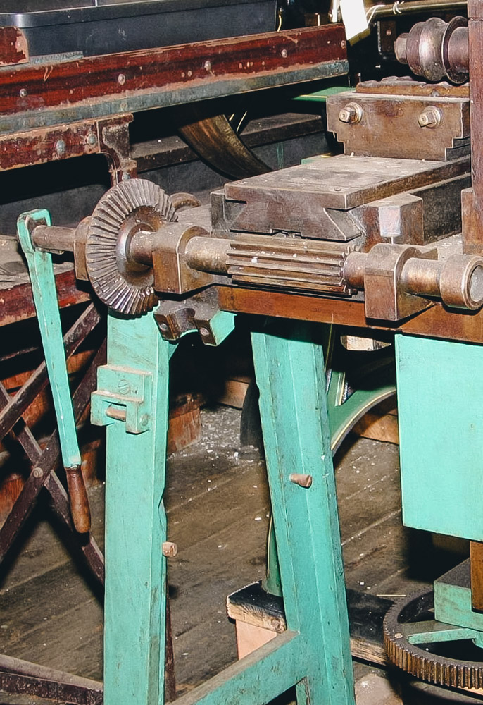 Since much of the feed mechanism was removed, the feeding was done manually. The lever attached to the wide gear fed the workpiece under the cutter. The present lever may have been made from the previous lever on the right side of the machine, the one that was used to engage the power feed. If it was made from that lever, it would have required the combined skills of a blacksmith (in the form of a welder, perhaps) and a machinist.
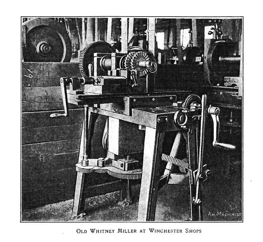
 Keneth L. Cope’s book on milling machines has a picture of a very similar machine that is believed to have been made by the Whitney Armory (which was in business from 1841 – 1848), still being used in 1911 at Winchester Arms. In place of the flat belt pulley on the left of our machine, the one at Winchester had a spur gear of about the same diameter. This seems to be the same situation as in the patent drawing. With its deep shadows, the picture of the machine at Winchester doesn’t clearly show how the power was supplied to the spindle and feed mechanisms. No connecting gears are visible. (Interesting how Winchester kept their machines in stalls, like large animals!)
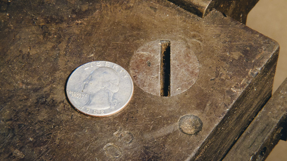
It’s also remarkable how Robertson used slotted-head screws instead of square or hex to hold the machine together.
The screws are flush with the surface that they are binding, which is nice, neat and smooth. Trying to use those screws, that is, to tighten or unscrew them, would no doubt have involved a powerful screwdriver. The screw heads are about 1 inch wide with the slot 1/8th inch across and 1/4 inch deep. I have never seen slotted-head screws nor a screwdriver so big. Maybe it was shaped something like a small garden hoe. Or, it could have looked like a giant letter “T.”
Even with that slot to receive a big screwdriver, a square or hexagonal bolt head is a much stronger way to turn a screw.
stay up to date
Want more content from the American Precision Museum?
Sign up to receive news straight to your inbox!
By submitting this form, you are consenting to receive marketing emails from: . You can revoke your consent to receive emails at any time by using the SafeUnsubscribe® link, found at the bottom of every email. Emails are serviced by Constant Contact
