Blog
Tool of the Month: Robbins & Lawrence Lock Plate Gage Set

by John Alexander, Collections Technician
So Many Slots, So Little Certainty: Inside a 19th-Century Gage Set
Imagining Precision Before Precision Tools
Just think: if you were living in the early to mid-1800s and were involved with making copies of any object, how would you be thinking of gaging parts so that they would fit together? Modern ideas of gaging parts are so far from what was available then that it’s pretty hard to imagine ourselves in their mindset. Robbins & Lawrence, who built the building that now houses the American Precision Museum in 1846, are credited with making some of the first interchangeable-part rifles using machinery. That seems to be true, but they didn’t just spring forth from birth, making wonderfully accurate, harmonious parts.
Thomas Jefferson saw the armory work being done in France, where he was our ambassador during our Revolutionary War, and wrote back with some urgency about how useful interchangeable rifle parts would be on the American battlefield. Various conversations took place within the US federal armories and between them and the contractors supplying the Army. Progress, in the sense of positive change, was slow.John Hall made breech-loading flint-lock rifles with interchangeable parts. He completed his first “production” pieces in 1820. They were fitted by skilled men with files. The machines that they had to work with weren’t accurate enough to do the finish work. It was also true that the men with files weren’t fast enough to finish very many rifles. An entire army couldn’t be equipped using their techniques.
Commonly, a single finished weapon would be designated as the “pattern” or “model,” and all parts made in the factory would be expected to fit that gun. But what would “fit” mean? How about if a contractor wanted to have a shaft pass through a hole in a plate and not bind? That’s easy; make the shaft narrow or the hole broad. Maybe both. There are places in a mechanism, such as a rifle lock or a milling machine, where it’s desirable to have a good, close fit. Of course, the “large hole, small shaft” policy doesn’t work there.
Some workers are capable of using old-style measuring tools consistently and precisely. The work that they turn out can be consistent, too. But the newer styles of tools make a difference. They can measure dimensions that the old tools can’t. They are often easier and faster to use (meaning that a worker can produce better results with less training,) and in many cases, they are overwhelmingly more accurate.
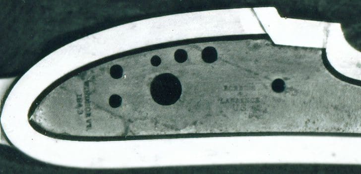
By the time Robbins & Lawrence bid for a Government contract in 1844, many ideas and tools similar to today’s had been developed. We have a photograph (I don’t know where it came from) of a set of gages for a rifle of the Robbins & Lawrence era. There’s a gage that contains a lockplate down on the right. Blowing up the picture, you can see right there in the middle, the words “Robbins / & / Lawrence / U.S.” in four lines. On the left of the lockplate, at right angles to the company name, it’s marked “Windsor, Vt.” To the left of that, it seems to be “1849”. (That figures since the company name was “Robbins, Kendall & Lawrence” before 1849.)
Richard Lawrence, co-founder of R&L, wrote in a memoir:
“In manufacturing Govt. Rifles a loss of about 38% was considered for bad material and workmanship.”
Now, that is something of a shock: over 1/3 of the work was failing inspection. And that information comes from someone we think of as an innovator in precision. Lawrence continues:
“About this time the California Gold excitement was raging. Guns were in great demand. We sold all of our second quality work and good mixt with it, anything to make up the gun for the full Govt. price.”
Lawrence wrote that this kept the company from financial disaster.
There are so many gaging surfaces in the box, but where are the gages for the rest of the gun? Things like the spring clips to hold the barrel bands in place. Gages for the sights, the cast brass butt plate, the patch box. And, of course, the stock had to be gaged too. Most of those in the picture could be for the lock and firing mechanism. There are all the holes in the plates, but there aren’t any of what we would call “plug gages” or “pin gages” (accurately polished round rods a few inches long), with three possible exceptions. Maybe another level to the box holds the rest of the gages. Maybe there’s another box.
How many slots and holes would be necessary to prove that an individual gun was in compliance? I counted 83 holes and 89 slots in the box! As if that weren’t enough, many of the slots have steps in them, and a number of the holes have a wide chamfer. It could be that some of those slots are redundant. Maybe they are meant to be used when the first hole or slot of a given size becomes inaccurate: too wide from having been worn in use. Maybe a chamfer on a given hole indicates that it has worn so much that it can’t be used anymore.
How could the user keep track of which opening is which? The various gaging openings aren’t labeled for a machinist or inspector to ensure that the correct gage surface was applied to the part being checked. Would that be so that only the specially trained and authorized inspectors could understand and use the gages? Just looking at the contents of the box makes me flinch, imagining what the “old-time” machinists must have seen in it. It must have been hard for most of the older men working then to adjust to a new world where everything was so strict.
Since the early 1800s, there’s been that term that’s still in use, “Luddites,” for folks who haven’t responded positively to their employer’s demands so they accommodate “modern” innovations. There were many in the mid-1800s who had similar attitudes. In the early days of the 21st century, I heard more than one retired machinist expressing the employees’ pride when they forced the company they had worked for to abandon the metric system.
And there’s one thing that the picture of the gages doesn’t clarify at all. What did they have as tolerances? There are some measurement questions along this line, too. For instance, how could you know or even specify a limit for a curve that changes over its length? As in the case of the “pocket” gage holding the lockplate in the photo, you would obviously want the lockplate to go into the pocket, but how would the question of minimum size be handled? Would you feel around the piece in the pocket with a shim, rejecting the workpiece if the shim went in? Could there be different tolerances for the various curved sides of the part?
Pretty nerdy stuff! Isn’t it fun?
stay up to date
Want more content from the American Precision Museum?
Sign up to receive news straight to your inbox!
By submitting this form, you are consenting to receive marketing emails from: . You can revoke your consent to receive emails at any time by using the SafeUnsubscribe® link, found at the bottom of every email. Emails are serviced by Constant Contact