This machine cut the spiral grooves inside the barrels of rifles and sometimes pistol barrels. The owner was David Hall Hilliard 1805-1877, who also owned and operated the barrel reaming machine that was the subject of the previous column. Hilliard “apprenticed” in the mid-1830s with Nicanor Kendall in Windsor, VT. The quotation marks accompany apprenticed here because Hilliard had already worked as a blacksmith and foundry pattern maker and would have known his way around a shop. In 1842, Kendall dropped out of gun manufacturing for a time. That’s when Hilliard established his own shop across the Connecticut River in Cornish, NH.
Blog
Tool of the Month: Hilliard’s Rifling Machine
Written by John Alexander, Collections Technician
This machine has been through a few owners. Only a sketchy outline based on hearsay exists. It goes like this: after the shop closed, an employee bought the machine in 1908 and gave it to the Jones & Lamson Machine Co. of Springfield, VT. J&L displayed it for many years in a lobby at their factory. Like so many other machine tool manufacturers in the US, J&L underwent several ownership changes. It was probably at one of those changes that the Museum was given the rifler.
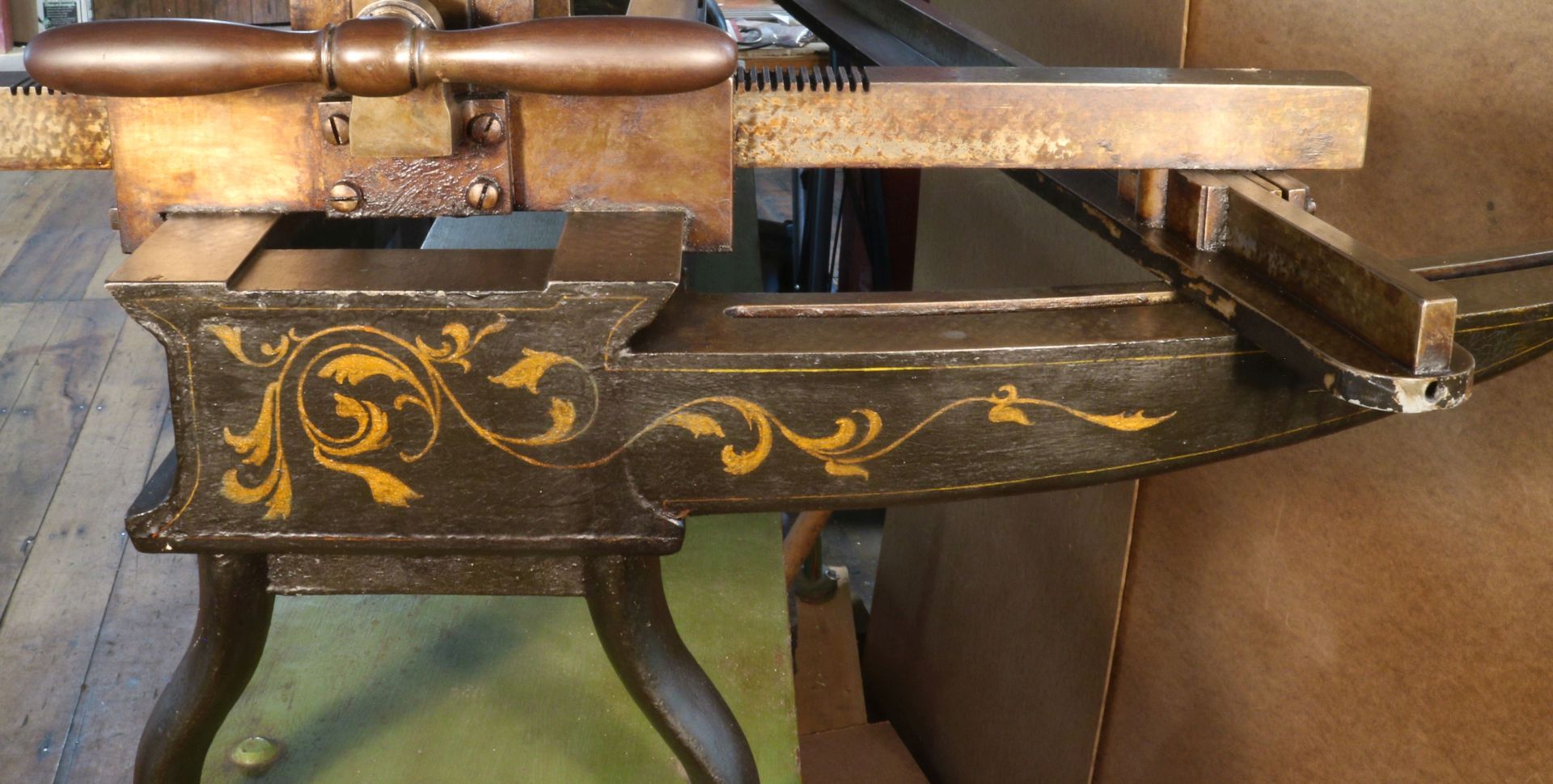
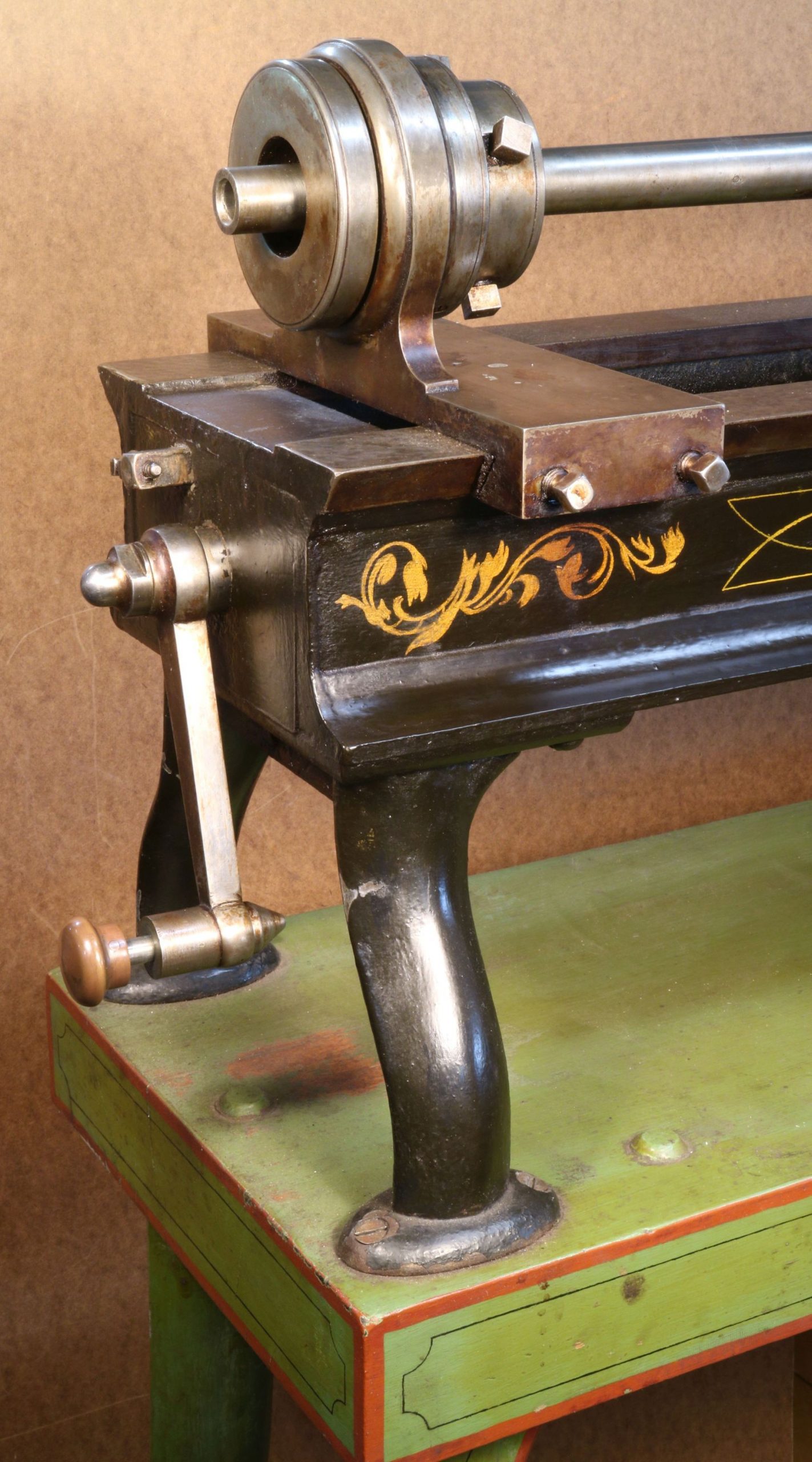
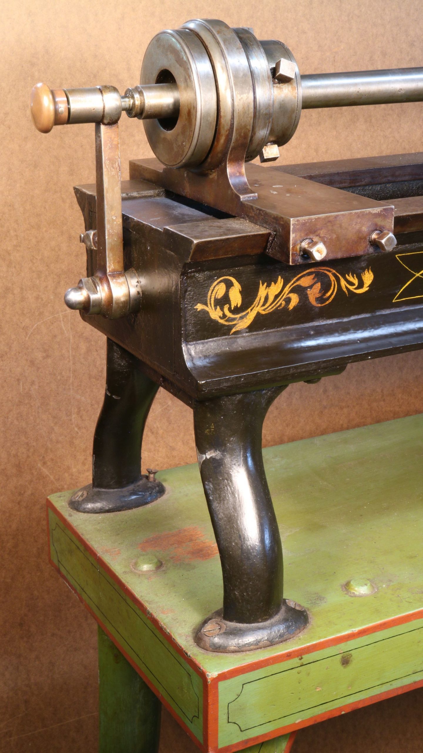
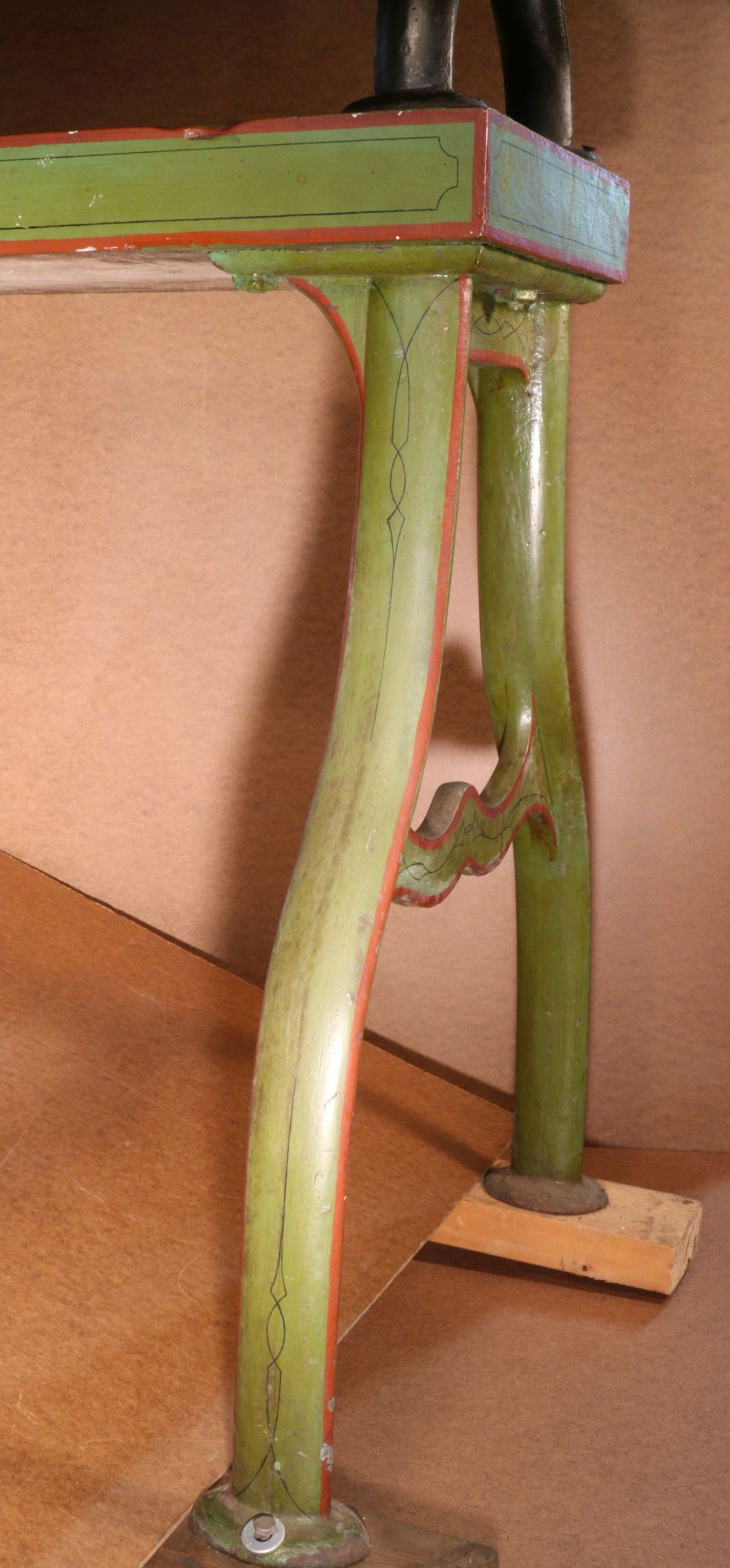
Visitors who see this machine on a Behind the Scenes tour usually comment on the fancy and interesting paint job. If they are mechanically experienced, they also notice that it is scraped over the sliding surfaces. These things didn’t typically happen in a rural gunsmith’s shop in New Hampshire. An antique expert said emphatically that the decoration didn’t fit with the machine’s provenance. It’s improbable that a gunsmith in rural New England in the second half of the 1800s would have any machine with a scraped surface unless it were absolutely necessary. It’s much more likely that both the painting and the scraping were done by J&L, pretty much as ornamentation.
So, what is “scraping” in the context of machine finishing? A technician cleans the surface to be scraped. They then wipe a very thin layer of blue paste over another surface that’s known to be straight, press it very carefully onto the surface to be scraped, and then lift the straightedge off. The blue goo transfers onto the high points. Then, the whole surface is made uniform by literal scraping: pushing a chisel-like cutter (the scraping tool) across the surface in short strokes until the high points are uniformly distributed to give accuracy and broadly enough to provide good support.
The spaces between the high points are also used in most applications to give little pockets of oil to keep friction down.
Scraping, done skillfully, can yield a wonderfully accurate surface. There are many more aspects of a machine that a scraper has to deal with sometimes. But machines structured as simply as this rifler don’t make many demands on them.
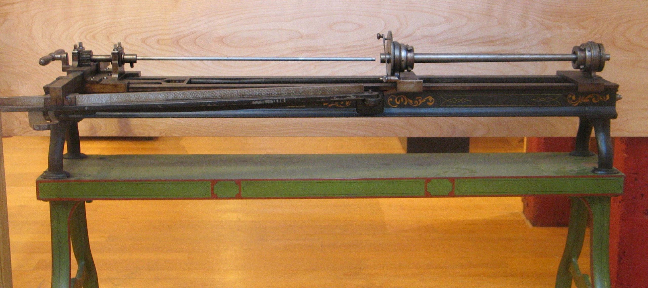
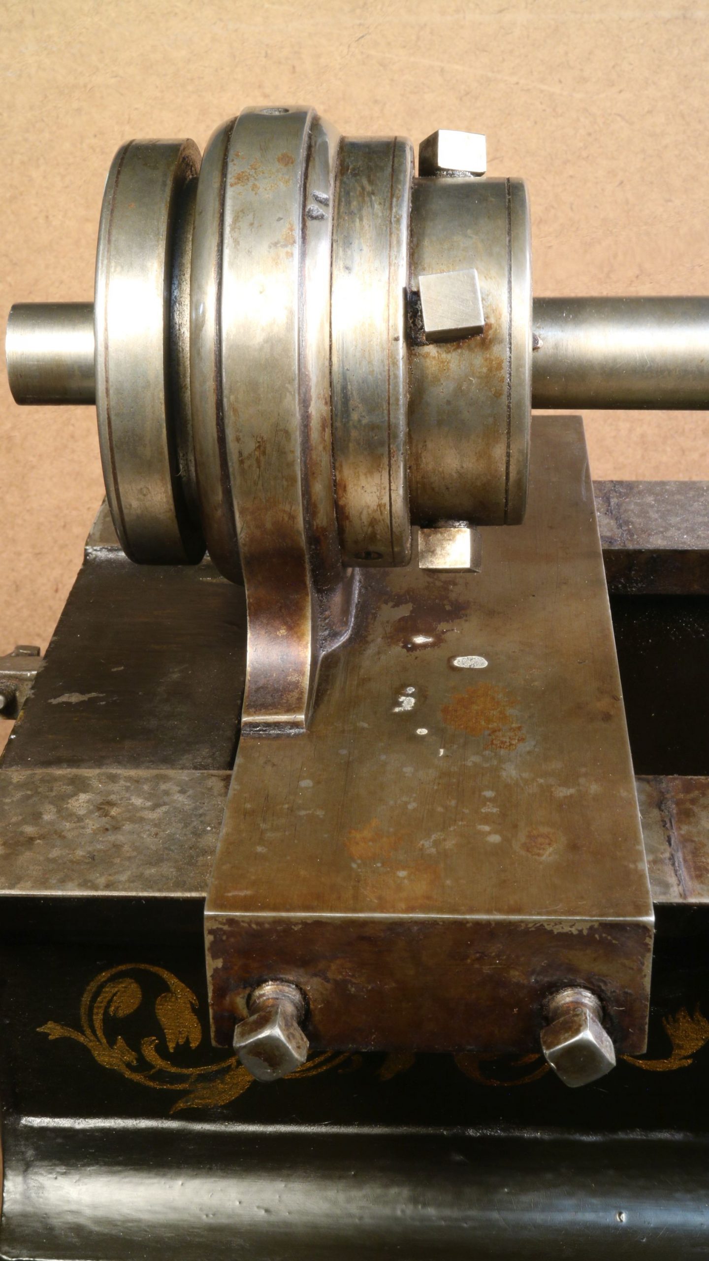
This machine’s mechanism is similar to that of our pistol rifling machine. Both have an adjustable sine bar to determine the rifling’s twist rate. The sine bar (in the case of both machines) is a surface that a slipper follows when the carriage is pushed along the rails. Since the sine bar and rails aren’t parallel to each other, the sine bar pushes the straight bar with the gear teeth (the rack) toward the rifling rod, which is in the middle of everything. The motion of the straight gear turns the round gear (the pinion), and thus the rifling rod, clockwise.
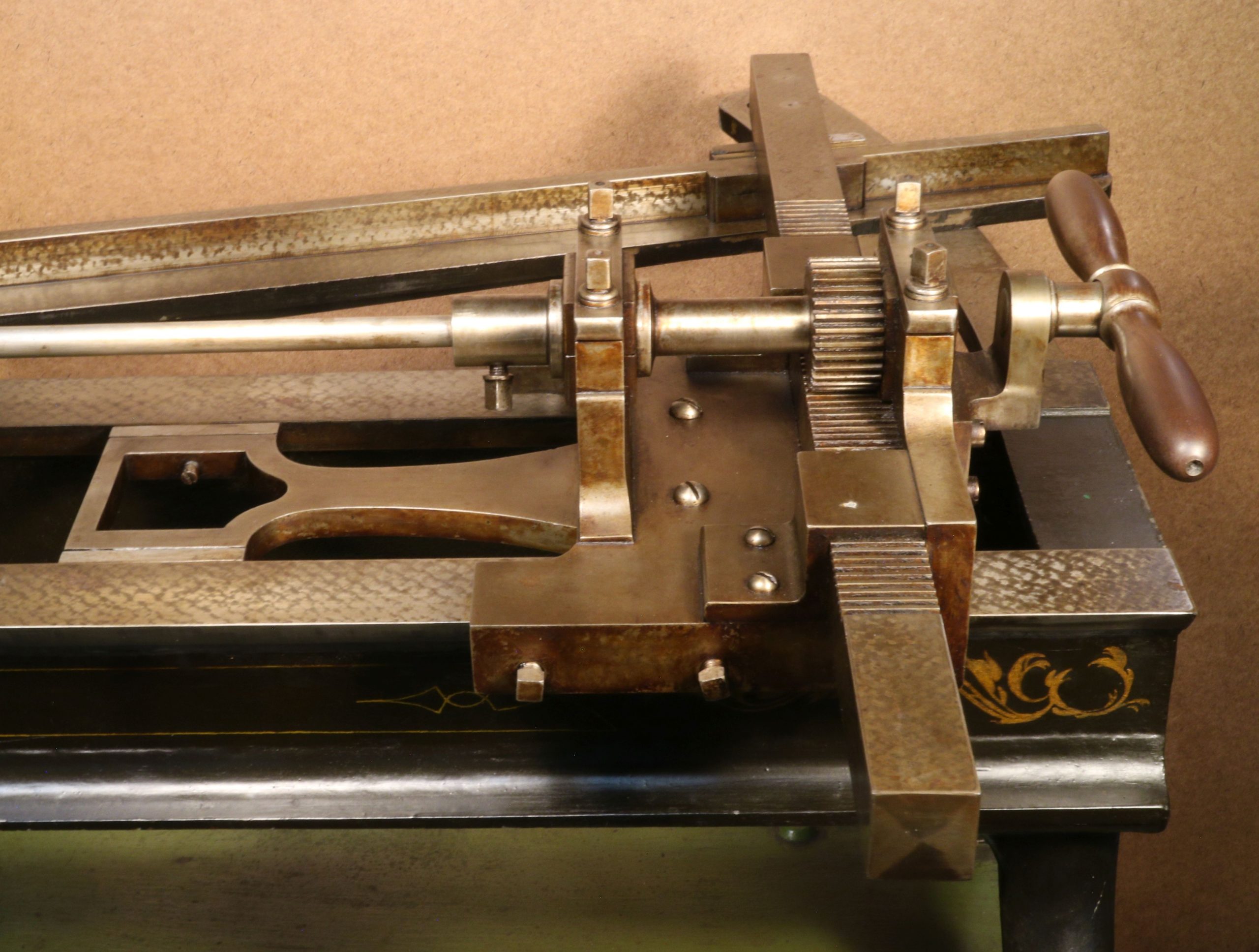
As the operator pulls the rifling rod back out of the barrel, the actual cutting occurs. The rod twists counter-clockwise. Our founder, Ed Battison, said that that mechanism originated here during the time of Robbins & Lawrence, emerging from the fertile mind of supervisor Frederick W. Howe. That system of dictating the twist rate was still being built into machines in the 20th century, and it’s not known how long it has been going on.
Aside from that sine bar with rack and pinion, this machine is notably simple. One way this machine was different from the pistol rifler was that it was human-powered and human-adjusted in terms of the depth of cut. The operator would hold the two handles, push the rifling rod through the barrel, and then pull it back out. After one or a few strokes, the operator would leave the handles and take several steps to the side of the machine and rotate the barrel by turning the disc in the middle (called an index plate) and put the pin in the next hole, thus putting it into position to have the next groove worked on.
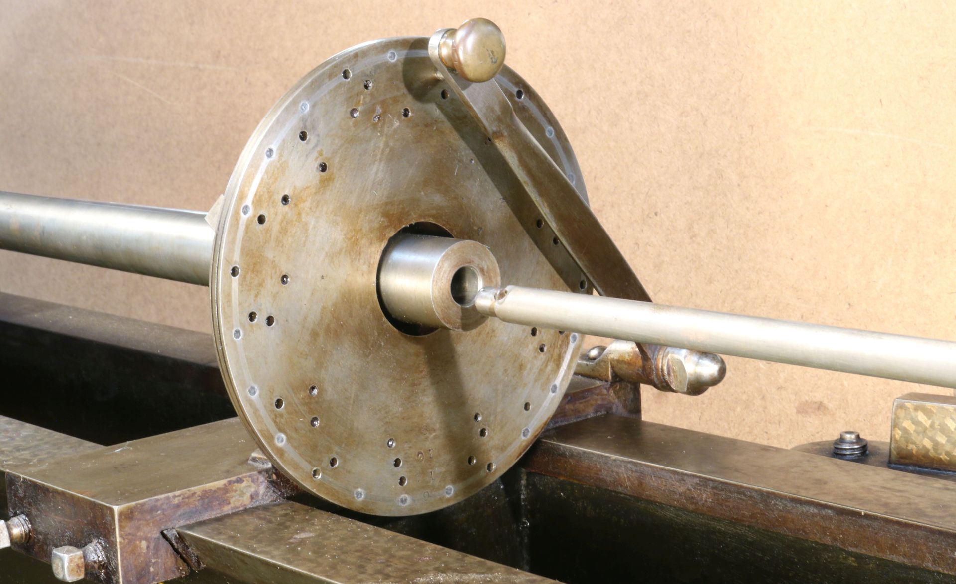
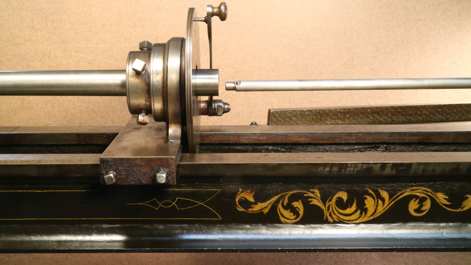
After working this way around the index plate, the operator would adjust the rifling rod, deepening the cut just a little. Then, the whole process would be repeated until the full depth of the grooves was reached. Clay Washburn, a volunteer at the Museum, said that he’d heard that there was a substantial trough worn into the floor at Hilliard’s from all that walking that was done over the years. So, what’s the swinging gadget at the left end? It’s to help center the barrel in the support bearing by using the four square-headed set screws.
An interesting feature not seen elsewhere is that these little round dots are in various places in the unpainted ironwork. Some are gray, a different shade from the iron, and some are white. They are holes that have been filled with lead. Apparently, bubbles formed in the iron when it was molten; the bubbles made holes when they cooled. There are at least two things that this filling could fix. One is that it would keep dirt from accumulating in the holes, perhaps keeping the machine running more often. The other possibility would be that the lead would help to make the machine look good. It’s better to have a neat machine when you show customers what you are up to. Of course, both were probably true.The fact that these filled holes aren’t usually seen makes one think that good foundry practice prevents such holes. Looking at the holes on several parts of the rifler, it seems that the foundry process could have been done with the other side of the part being “up.” That would put the holes, if any, on the “down” side, where they would be unseen and would be unlikely to interfere with the operation. Since Hilliard had worked as a foundry pattern maker in his younger days, it’s surprising to see these defects on the surface.
Among the many questions we will never know the answer to: What kind of bench did it sit on? Below the 7” legs on the bottom of the machine, there’s a heavy board about 70” x 12” x 2 ½”. Below that, there are cast iron legs. Those cast iron legs are standard issue legs from when the machine was made. But knowing that it worked in a very rural shop raises the possibility that the legs were added later in its life by J&L. It seems easy to imagine the rifler was originally on a good, solid wooden bench, carpenter-made for economy’s sake.The machine is pretty grubby looking, and I’m sorry about that. At first glance, one might be tempted to think that it’s very rusty, but that’s not so. There are a fair number of small rust spots, but most of the discoloration on the iron is from a greasy coating that was put there a long time ago to keep it from rusting. It would be nice to use solvent to remove the coating and re-coat it with something more transparent and not so thick, but that would take considerable time. The machine isn’t on display now, so it has less priority. Maybe later.
stay up to date
Want more content from the American Precision Museum?
Sign up to receive news straight to your inbox!