Blog

Patterns and Molds

Patterns and Molds

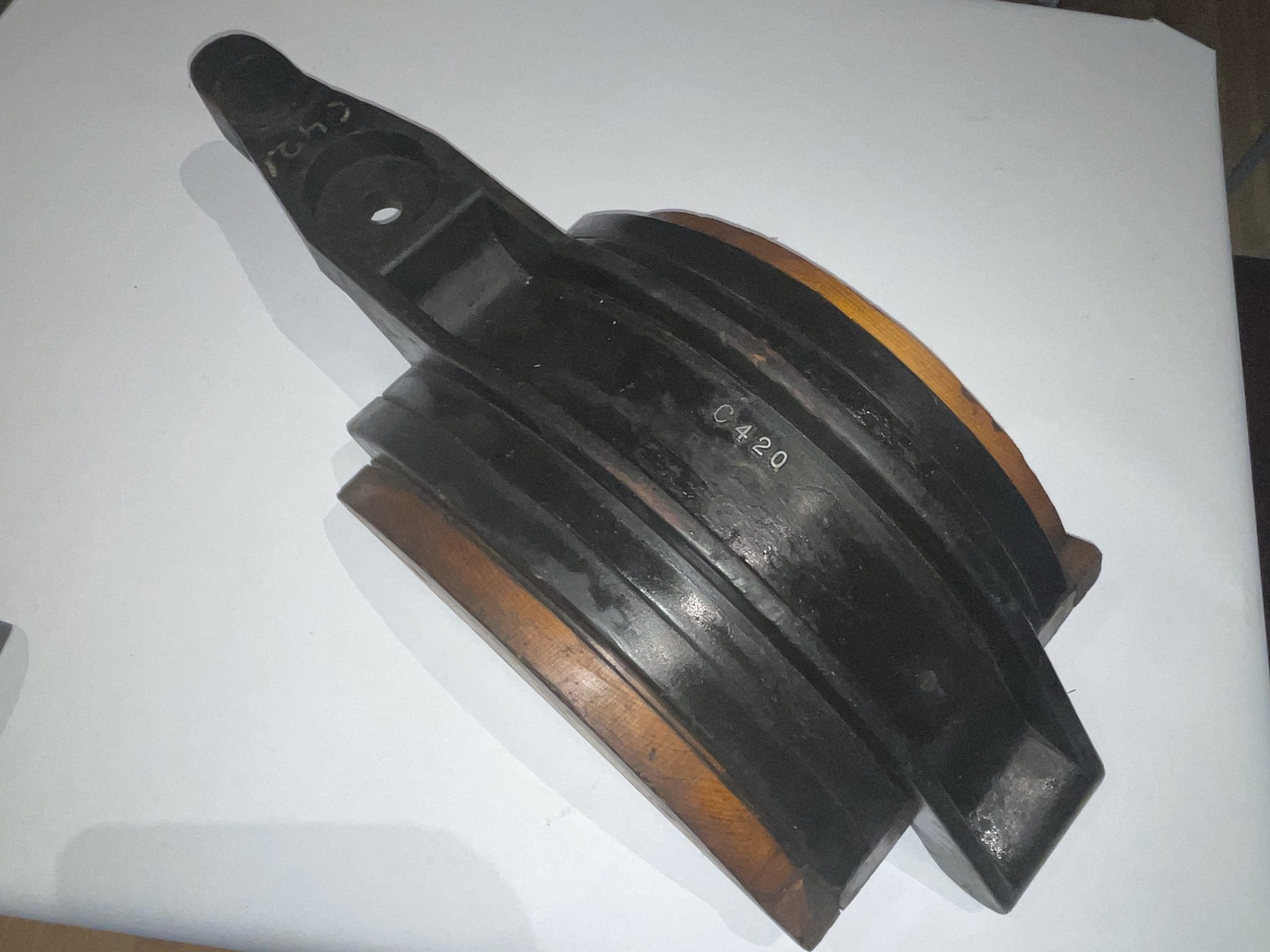
A pattern is the master copy of a design. Wooden patterns like these could have been used hundreds of times before losing their shape. Flat back patterns, like these wrenches, would press the flat of the pattern onto the bottom of the sand mold and then sand would be packed around it.  On split patterns like the hand wheel, both portions of the pattern would be pressed into the top and bottom of the mold and removed without hurting the mold.The mold would then be joined flawlessly to create a complex shape. The patterns are covered in a black paint to protect them from heat and humidity as well as conveying the finishing steps required.


These wrenches labeled 10,24,25 don’t line up with the metric, Whitworth, or imperial system of measuring.
Handwheel
This 9.75″ handwheel is part of a split mold with the other half missing.
The spokes’ width have been enlarged from the original pattern.
Globe Valve. A split part pattern in its first stage of the manufacturing process.
After it would be cast the sprues would be cut off, drilled out and tapped to fit pipes and valve handles.
A sampling of pattern-maker’s tools.
Elevator Brake. A wooden pattern produced by Geo. T McLauthlin Co.
Note how only the upper dimensions are painted black.
This six spoke wheel measures at 3’7″ in diameter.
Cone R2044 Pattern. This pattern made 4 of the same parts at the same time. Notice the part numbers, R2044 and WCB, being stamped into each part.
Both of these patterns are stamped by J. English, Hartland, VT.
This 2 spoked object was a part of a 3 part split pattern with a mirrored part meeting at the hub and an outer ring holding it together.
Graphite crucible. Graphite can withstand very high temperatures, so this crucible can be used to hold hot liquid metal.
Flask. Each half would be filled with sand, the pattern inlaid into the sand, and removed.
Line Shaft Hanger. A replica two-part aluminum cast used for the main driveshaft here in the armory. This cast was used as a test to check the accuracy of the mold before the iron ones were poured.
Counter Shaft Hangers. A set of 3 identical casts each in a different stage of the manufacturing process.
These counter shafts were used to transmit the motion from the main line shaft out to where it is needed.
Can you guess what the purpose of the red object on the end of the painted hanger is?


Audience:
Subject Matter:
Back

stay up to date

Want more content from the American Precision Museum?
Sign up to receive news straight to your inbox!


By submitting this form, you are consenting to receive marketing emails from: . You can revoke your consent to receive emails at any time by using the SafeUnsubscribe® link, found at the bottom of every email. Emails are serviced by Constant Contact