Blog
Machine of the Month: Profile of our Profiler
Written by John Alexander, Collections Technician
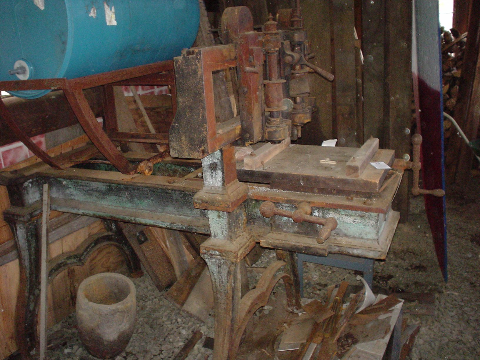
This machine was found by Jamie Swan, a longtime friend of the Museum, in a shed near a swamp in Connecticut. It didn’t look so good at the time, but Jamie saw that its nameplate was Jones, Lamson & Co. and knew it had been made by a company that was part of the Museum’s history. The Museum is very grateful to the machine’s owner, Earl Skokan, for donating it to us.
And there’s the Herculean task done by former trustee Bill McCarthy. Bill hauled the machine to his shop in Pennsylvania, deep cleaned and painted it, made some replacement parts for it, and then delivered it to the Museum. Whew!
Just a brief note here to clarify the chronology:
Robbins & Lawrence failed in 1856. They were succeeded by Vermont Arms 1856 -1857, who was succeeded by Union Arms 1857.
Then by Lamson, Goodnow & Yale, in 1858, the same company became E. G. Lamson, then Windsor Manufacturing, then Russell Jones bought into the company in 1869 or 1870, and it became Jones, Lamson & Co.
In 1876 the machinery manufacturing part of the company became Jones & Lamson and remained so until the 1990s, when it went out of business.
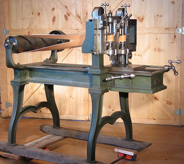
It’s very similar to the gunstock inletting machine at the other end of the building, except that, since the cutting forces are so much higher in metal than in wood, this machine gives the operator a much stronger means of controlling the path of the cut.
Another difference is that the profiler’s workpiece is only cut in two dimensions. Since it’s mainly designed to make a smooth edge around the workpiece, it’s also called an edger. The inletting machine also cuts in a third dimension, creating a recess (or several of them) in the workpiece.
Each of the two cutter and stylus pairs are moved vertically with a short lever that sticks out toward the operator in the middle of the machine. It lowers the cutter and stylus to operational height before cutting is started.
They are moved by the lever that’s to the left in the photo. The little lever on the right locks them in place. The slot in the bar regulates the maximum downward movement.The workpiece is moved toward and away from the operator with the left crank. The cutter and the tracing stylus move left and right using the right crank.
One of the machine’s most interesting mechanical features is in the gears that move the platen and, separately, the stylus with the cutter. The gears have a totally different system to get rid of slack. What looks like “thick gears” are really pairs of gears on the same axle. They have an adjusting screw so they can be rotated slightly relative to each other.
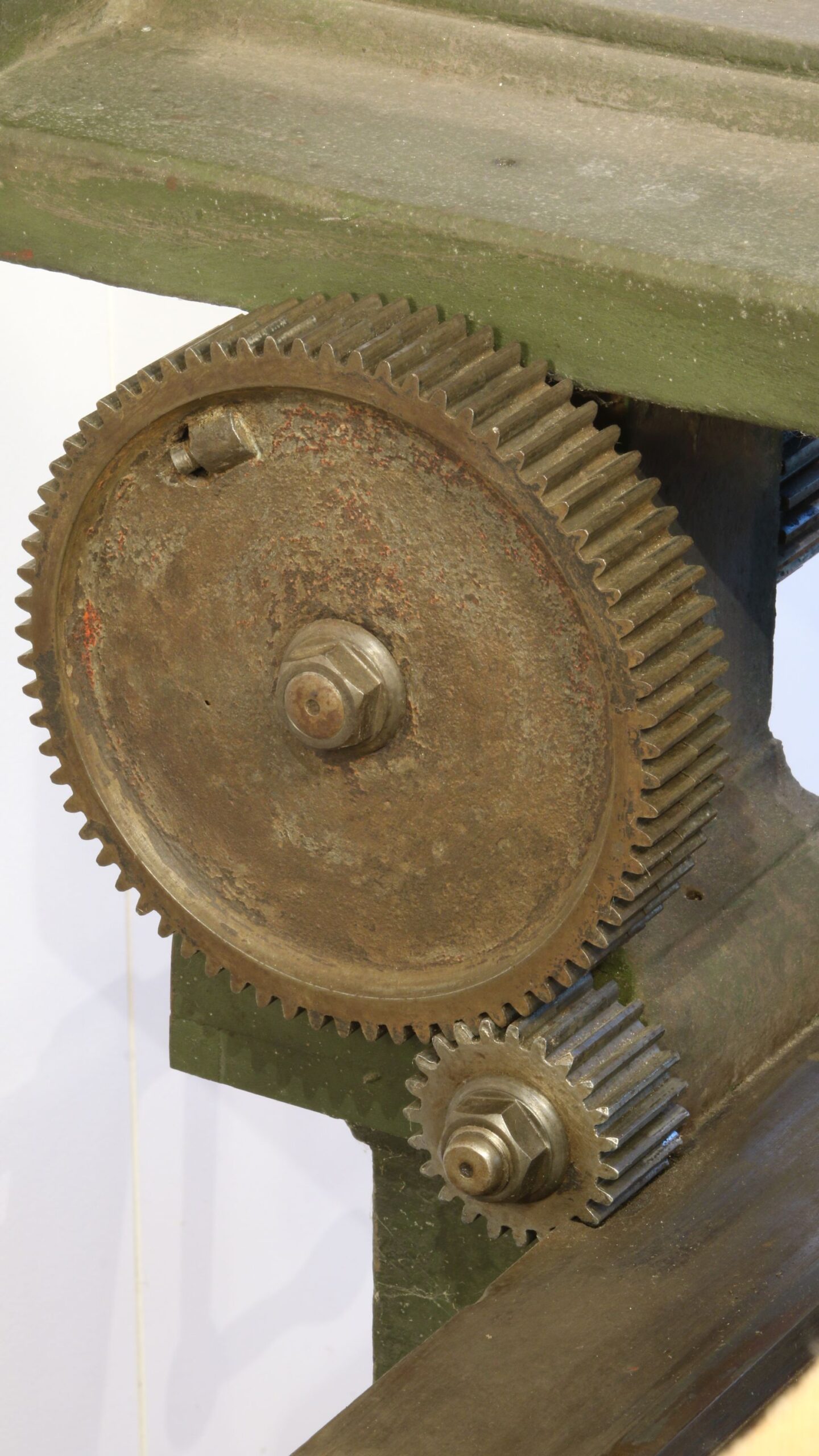
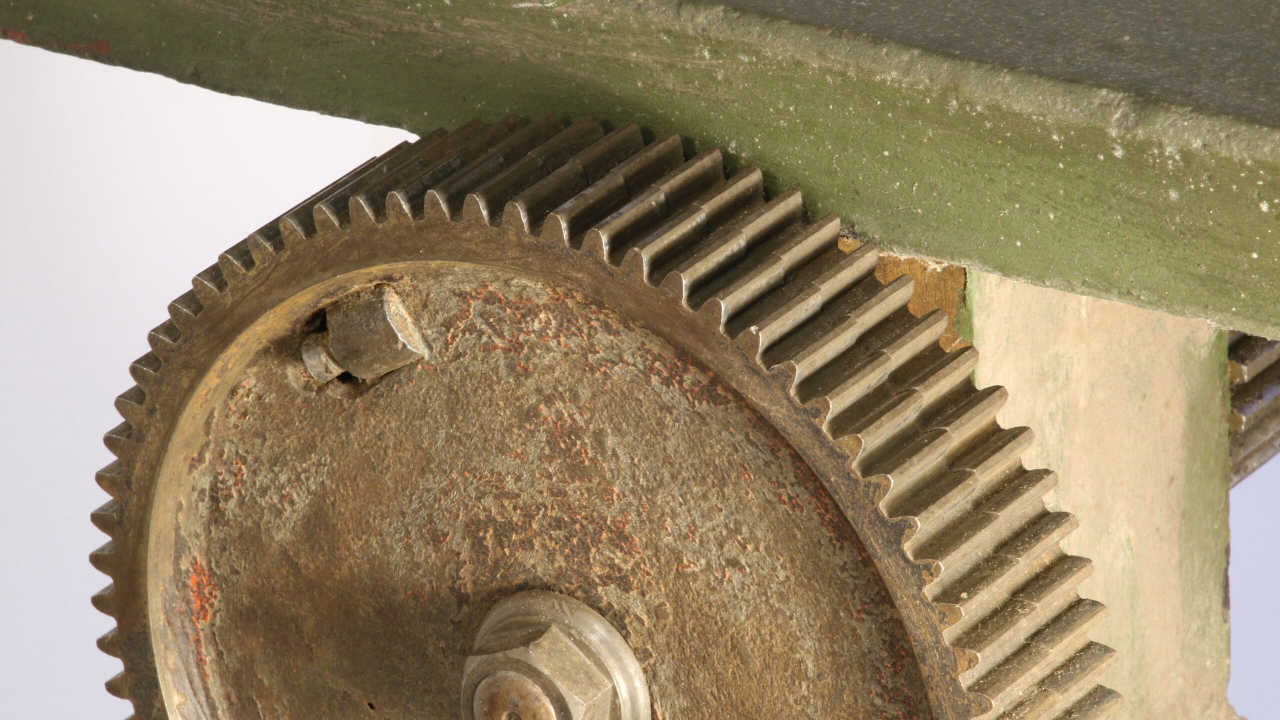
In this way, they can be moved so that the teeth of the rotating gears will completely fill the space between the teeth of the gear the pair is engaged with.
In one case, the straight gear that is above and to the rear of the right-hand crank, the straight gear (called a rack) is split down the middle so that it can be adjusted to get the same effect.
A split rack for the same purpose is on the pistol rifling machine at the other end of the exhibit floor. →
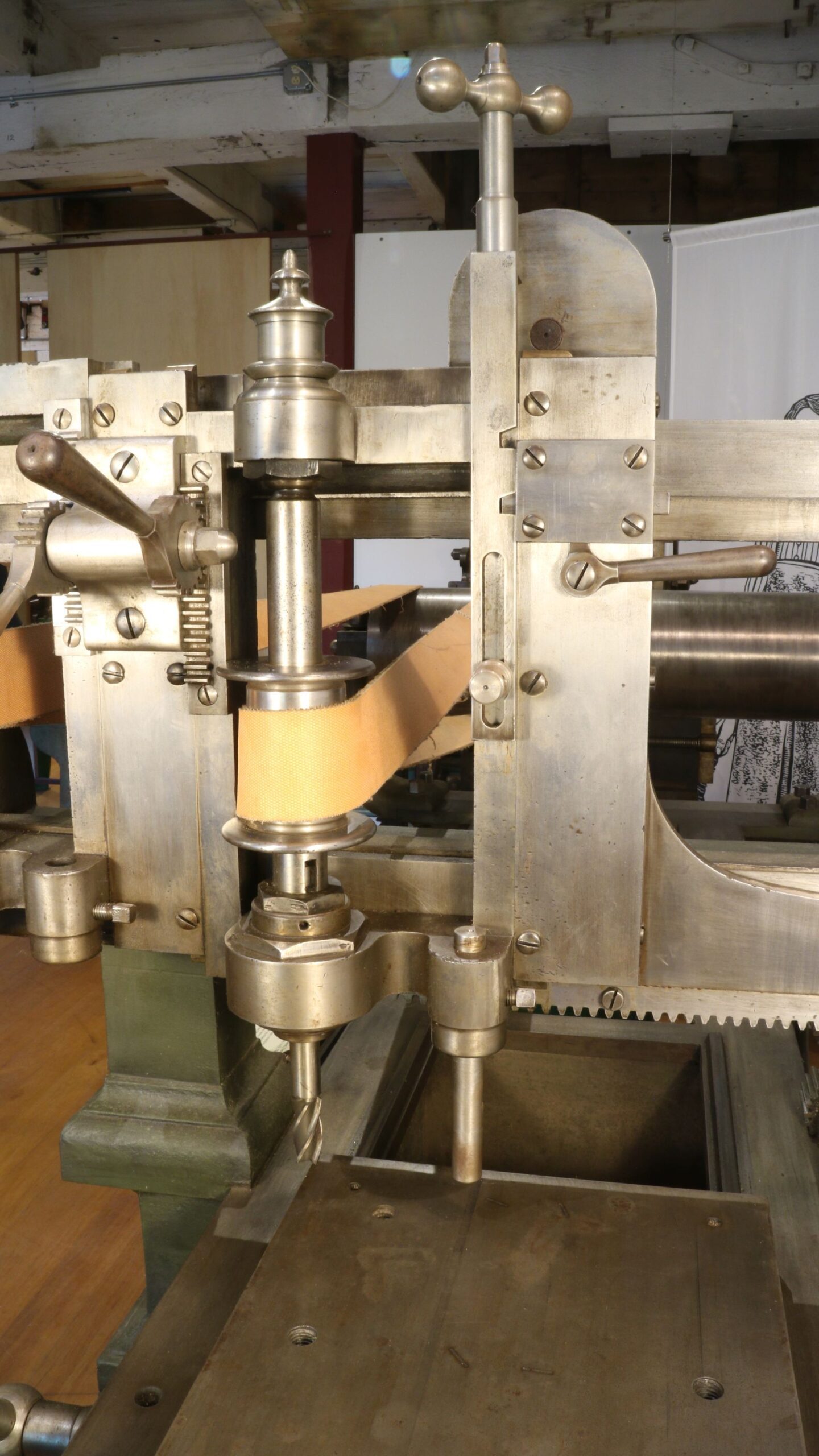 Cutter & Stylus Height Control
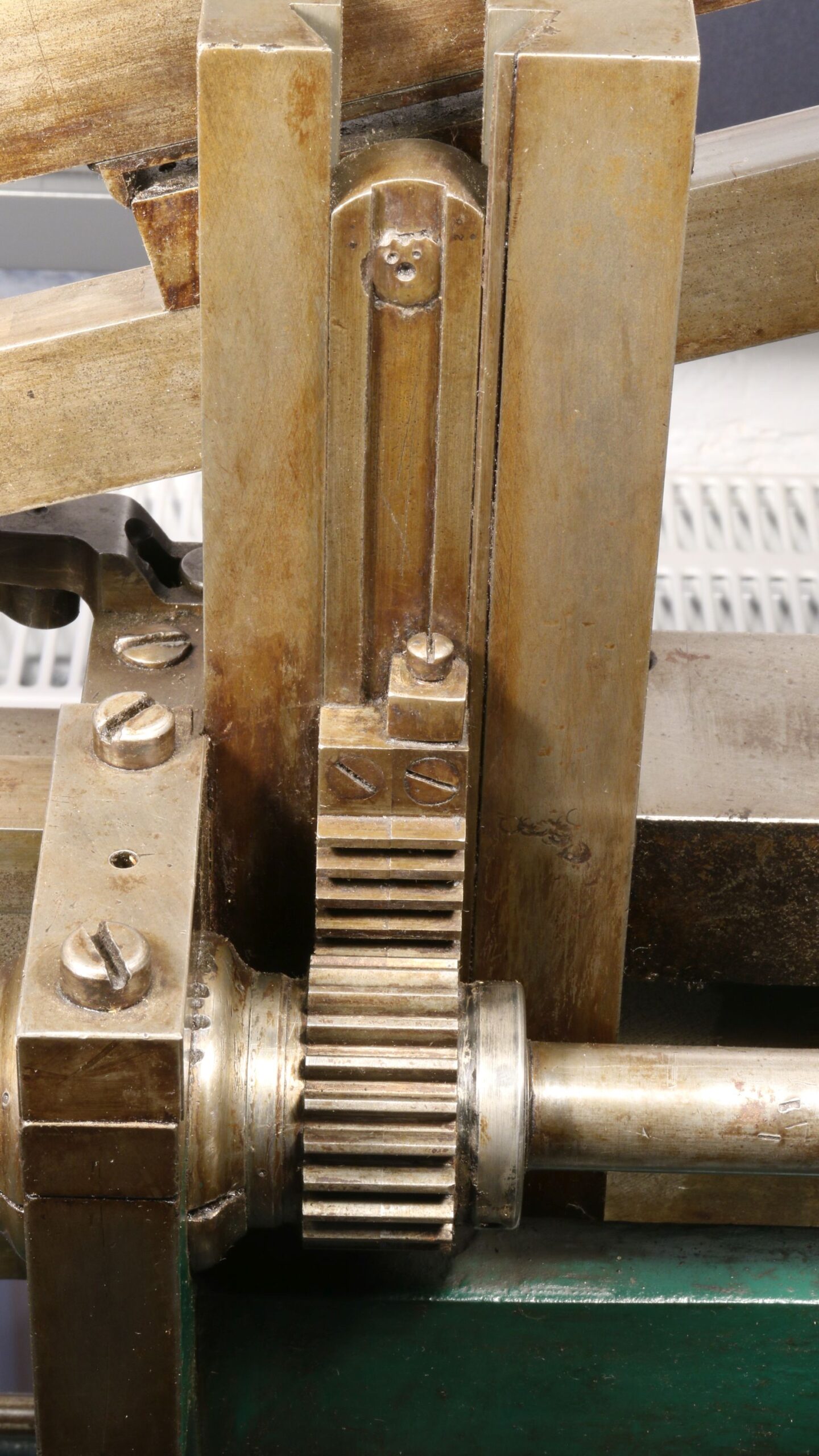
Anti-backlash gearing on our pistol-rifling machine.
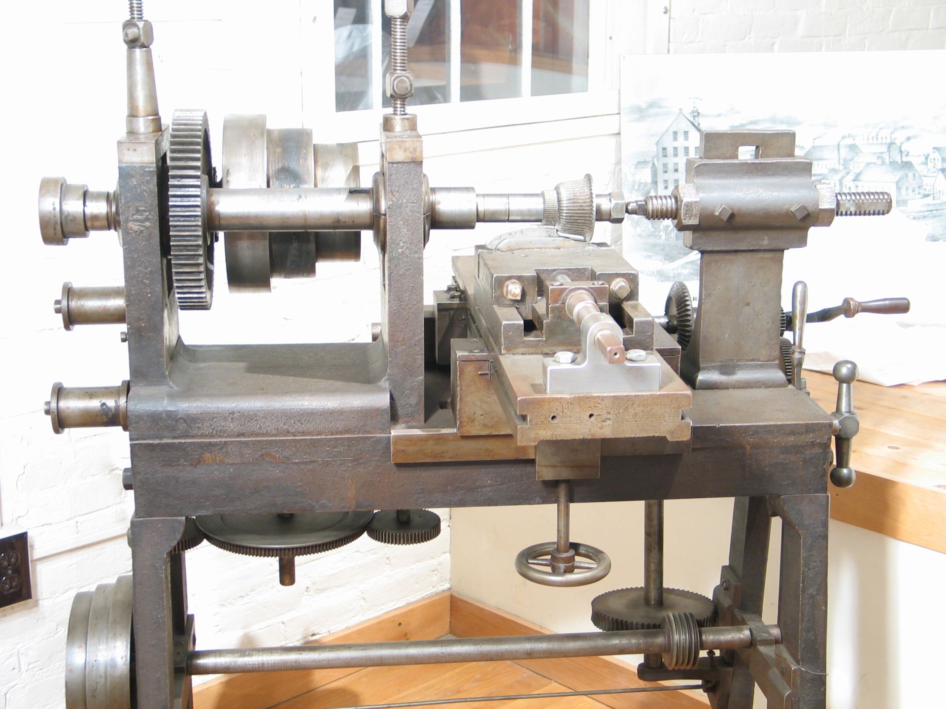
Also on display is a Howe-designed plain horizontal milling machine. Recently, we had it as our Machine of the Month. It’s the one that’s connected to the overhead lineshaft with a leather drive belt. It was designed at about the same time as the rifler and profiler. It uses a cutter that’s shaped to cut part of the edge of the lock plate of a muzzle-loading rifle.
What are the advantages of the two machines? The profiling mill is a much more complex, bigger, and expensive machine. The horizontal mill is useful for different tasks.
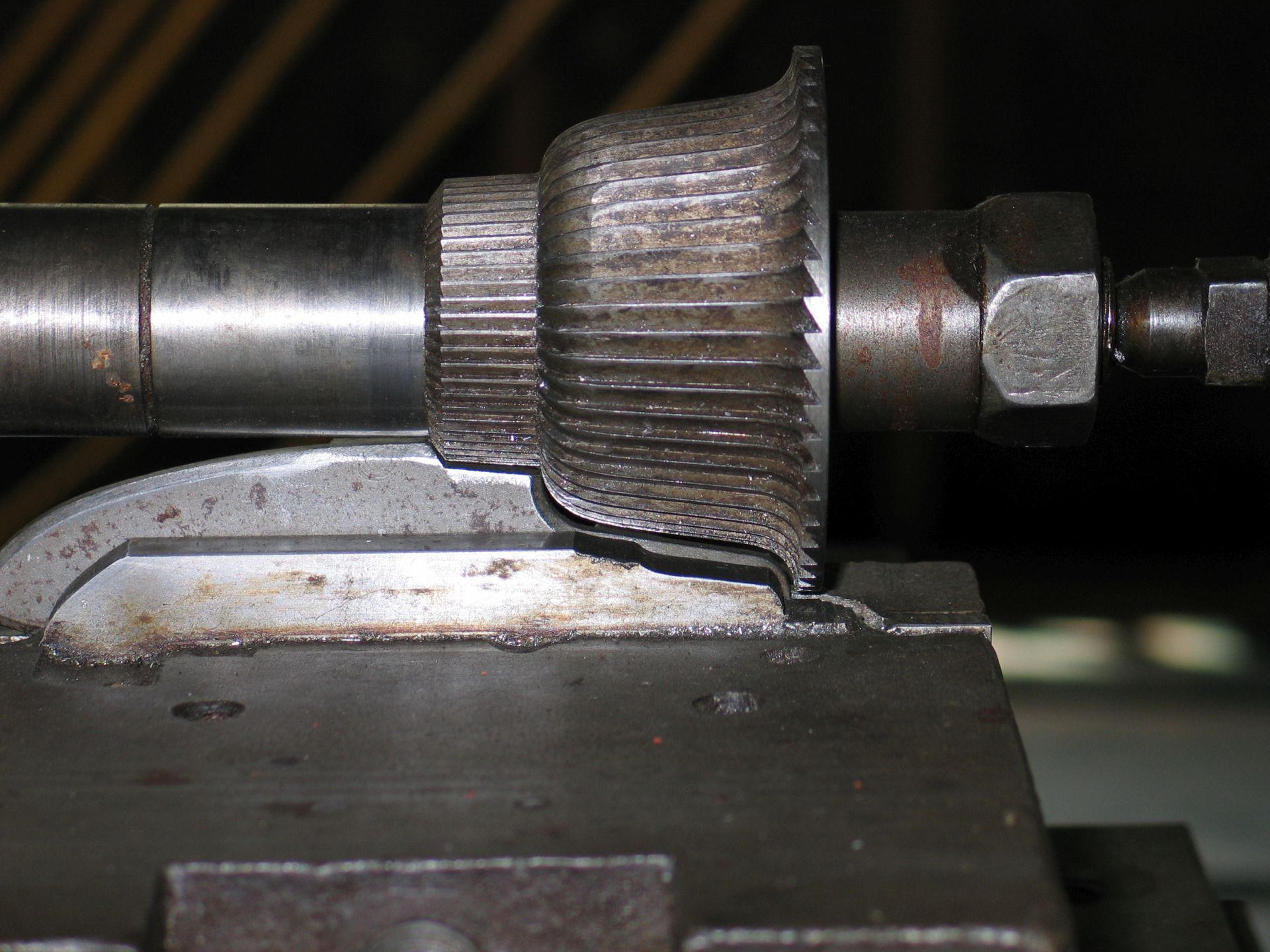
The problem for the horizontal mill is that the attractive formed cutting tool it is using would be difficult and wildly expensive to make (though not so bad now by using automatic machinery,) hell to resharpen, and will give a poorer finish. In fact, the finish would be so bad as to require a complete hand filing over the same surface to pass inspection.
That form cutter can be taken apart since it is actually made up of two pieces: the wavey one on the right and the (nearly) cylindrical one on the left. That makes it possible to resharpen, but sharpening would still be distressingly difficult, especially the curved parts of the teeth. There are a lot of teeth close together!
On the other hand, the profiling mill uses a very simple cutter with straight teeth or gently twisting ones. Those teeth don’t need to be so many or so close together. The cutters would be much easier to sharpen, and they’d have a much, much lower purchase price.
Because the shape that a profiler cuts is formed by having the stylus follow a pattern, the profiler’s whole workpiece can be edged in one operation using one tool. Several form tools would be needed to trim the edges all the way around a shape like a lockplate. The form tool that we have, with the big step in it, would be the hardest of the several to make and maintain, but the cutters to be used on the other parts of the lockplate would still be challenging to keep sharpened and working.
The form cutter would be tough to resharpen without the kind of automatic machinery that didn’t exist until long after 1850. Although it could be done by hand, those doing it would be among the most skilled workers, and there are never enough of them to go around. There’s always a reluctance to tie such a man up in doing such repetitive work since he will be expensive to keep on the payroll and be bored by the task.
As to finish, the form cutter is quite wide and would have almost all of one tooth actively cutting simultaneously. That’s a recipe for the cutter to chatter (to bounce in the cut), thus producing a poor finish on the workpiece and a short life for the cutter.
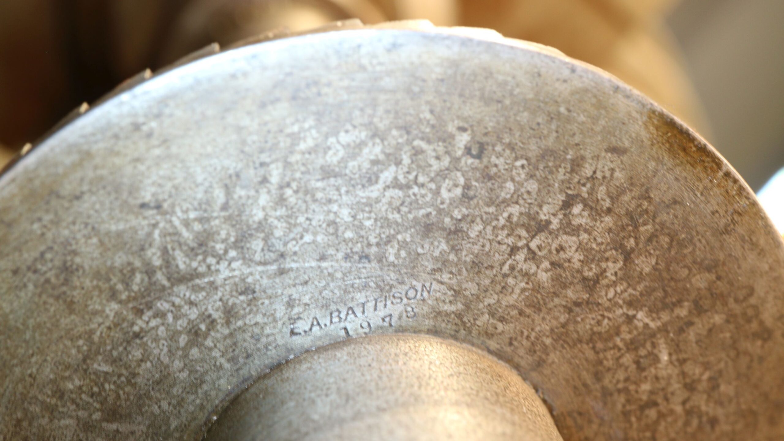
The cutter that’s on the horizontal mill now was made by Ed Battison, our Museum’s founder, in 1978. His name and the date are stamped on the large flat surface on the cutter’s right-hand side. The characters are small; his name is about half an inch wide.
The spiral-fluted cutter that’s on the profiler was also made recently. It’s an end mill tool that would be gotten off-the-shelf at a reasonably low price (less than $30) from an industrial supplier in the 20th or 21st centuries.
Another thing that would have been very important to use this cutter would be that around 1850, tool steel was relatively poor compared to what we expect nowadays. This would mean that the cutter changes to resharpen those many teeth would be distressingly frequent.
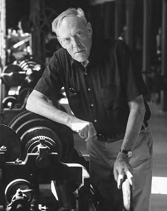
So why do we have such a large, problematic form tool on the horizontal mill? Probably because Ed Battison wanted to prove something for himself or for someone who had differing ideas.
Ed didn’t want to base conclusions on second-hand information. He often went to a surprising amount of trouble to prove how some machines worked under particular circumstances or how some process really was done.
stay up to date
Want more content from the American Precision Museum?
Sign up to receive news straight to your inbox!
By submitting this form, you are consenting to receive marketing emails from: . You can revoke your consent to receive emails at any time by using the SafeUnsubscribe® link, found at the bottom of every email. Emails are serviced by Constant Contact