Blog
Machine of the Month: No. 12 Lathe
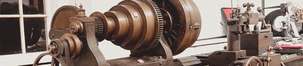
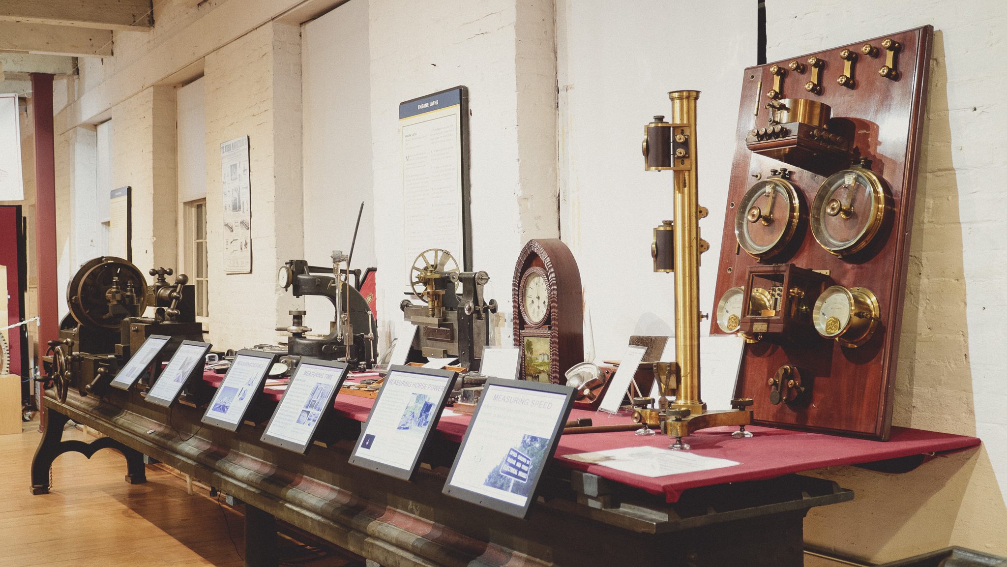
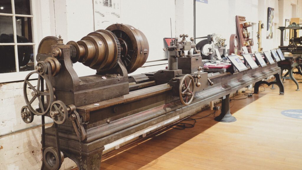 Some visitors spend some time around this machine before they realize that it’s a lathe. That’s because we use the rear half of its bed as a bench to display our measuring exhibit.

One thing that most people would agree on is that it’s a big lathe at 20 feet overall length. I usually tell people that it’s relatively long. There are a lot of special-purpose lathes in the world that are much larger.
Fortunately, we haven’t had to move any big machines like that. This one was complicated enough. Worried about the strength of the legs, we linked them together with full-length wooden sleepers. We moved it on machinery mover’s skates. Our set will support 5 tons. They have very little rolling friction, so it’s not hard to push something very heavy across a smooth, level floor.
There were a couple of places where the machine didn’t have space to go around one of the posts. The solution was to jack up the machine and turn the skates to a right angle of what they had been, get around the corner, then turn the skates back to straight and continue on. Note that the lathe had to be rotated 180 degrees in the course of the trip to its new place since it was moved to rest against the wall opposite from where it had started. I’d estimate that this lathe weighs around 2 1/2 tons. But that’s what you might call “just an opinion.”
Here’s a picture of the lathe after it had moved into position but not yet set down on the floor. That’s volunteer Steve Wright contemplating the situation—one of the many projects that couldn’t have been done without him.
There’s an adjustable foot in the middle of the lathe! For precision, that foot would have to rest on something completely stable relative to the feet at the ends of the machine. Our multi-layer wooden floor just couldn’t be good enough. It would have to be stone or concrete.
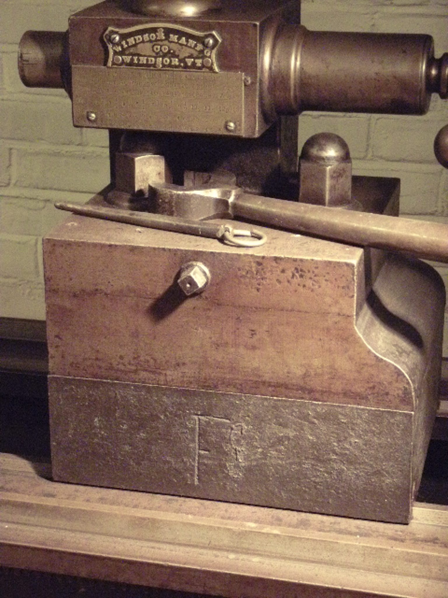
There is a pair of riser blocks in place on the lathe. They raise the headstock and tailstock about 4 3/8 inches. They have the letter “F” boldly chiseled into them. Using them enables work on a larger diameter workpiece. The maximum diameter would be about 29” now.
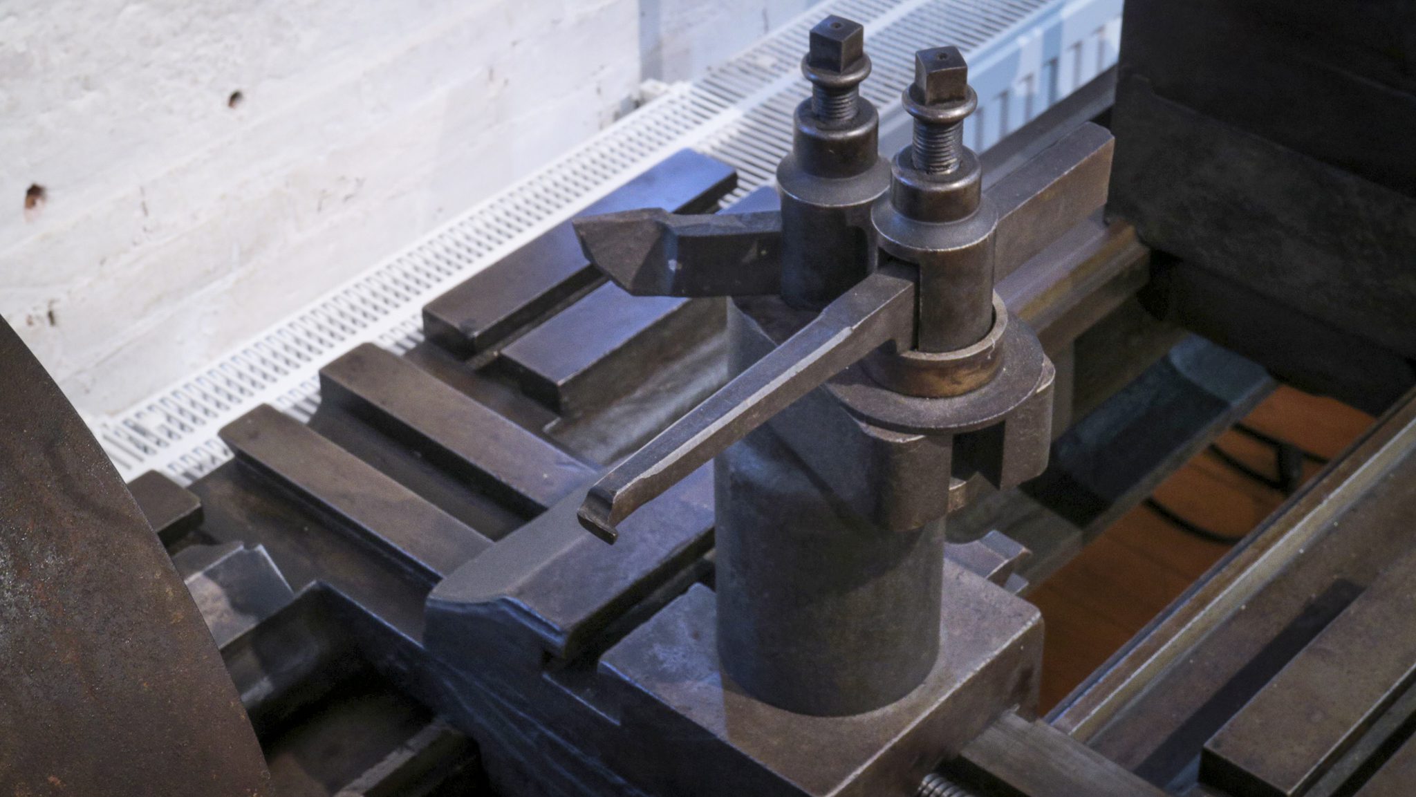 We have two tool posts that belong to this lathe. There’s the one that’s now on the machine, and another, smaller one that would be used if the machine was used without the riser blocks. The tool posts are unusual in that each has a both a hole and a slot for mounting tools. An operator could use them for boring out an existing hole with one of the tools and turning the outer diameter of the workpiece with the other one. This would be handy for repetitive work. The two of them wouldn’t have been used to cut simultaneously.
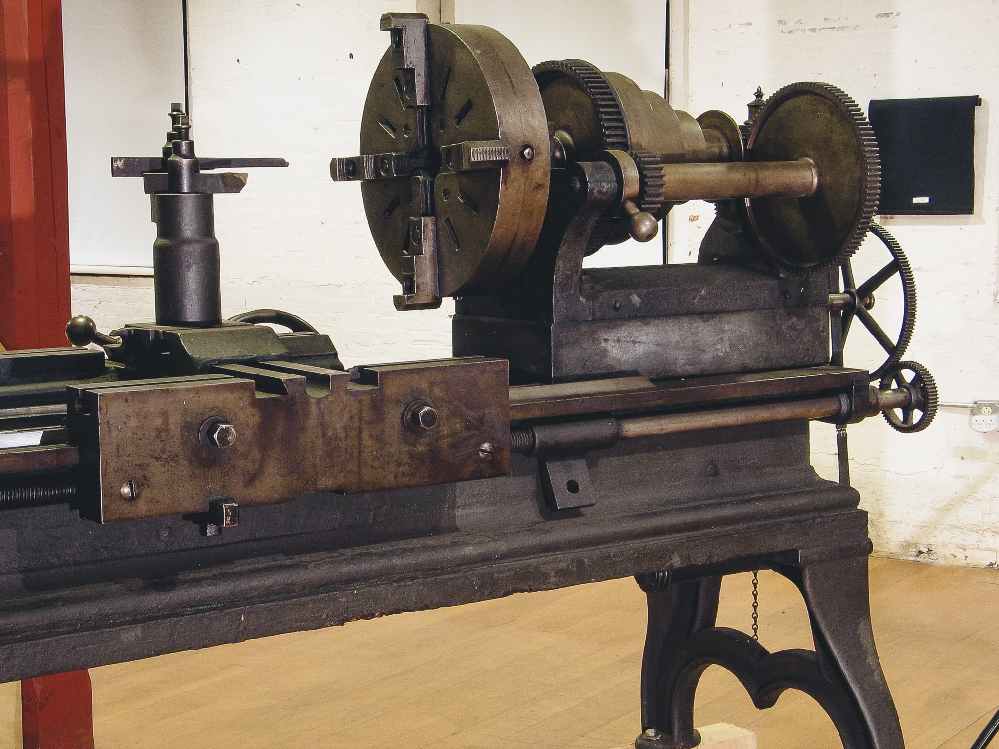 When this lathe was made, the general-purpose cutting feed and the threading feed were driven by separate mechanisms, as they are done now. But then, the threading feed shaft was (almost) always placed at the rear of the bed. This meant that the operator had to reach over or under the spinning workpiece to engage and release the threading feature. Very strange to modern eyes! The carriage doesn’t attach to the threading feed rod anymore. We don’t have the connecting pieces.
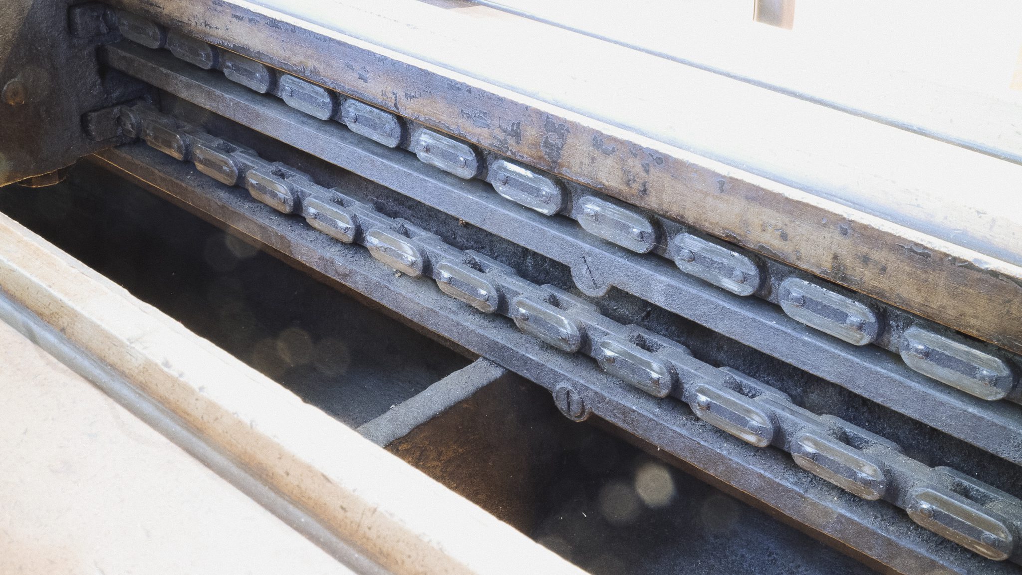 The general-purpose feed on this machine is moved by a chain, roughly similar to a very large bicycle chain. It’s tucked into the front of the bed. In a modern machine, both feeds are shaft driven and the controls for them are on the front of the bed. All in all, an interesting and still handsome machine.
stay up to date
Want more content from the American Precision Museum?
Sign up to receive news straight to your inbox!
By submitting this form, you are consenting to receive marketing emails from: . You can revoke your consent to receive emails at any time by using the SafeUnsubscribe® link, found at the bottom of every email. Emails are serviced by Constant Contact