Blog
A Watthour Meter at Industrial Scale
By John Alexander, Collections Technician at the American Precision Museum
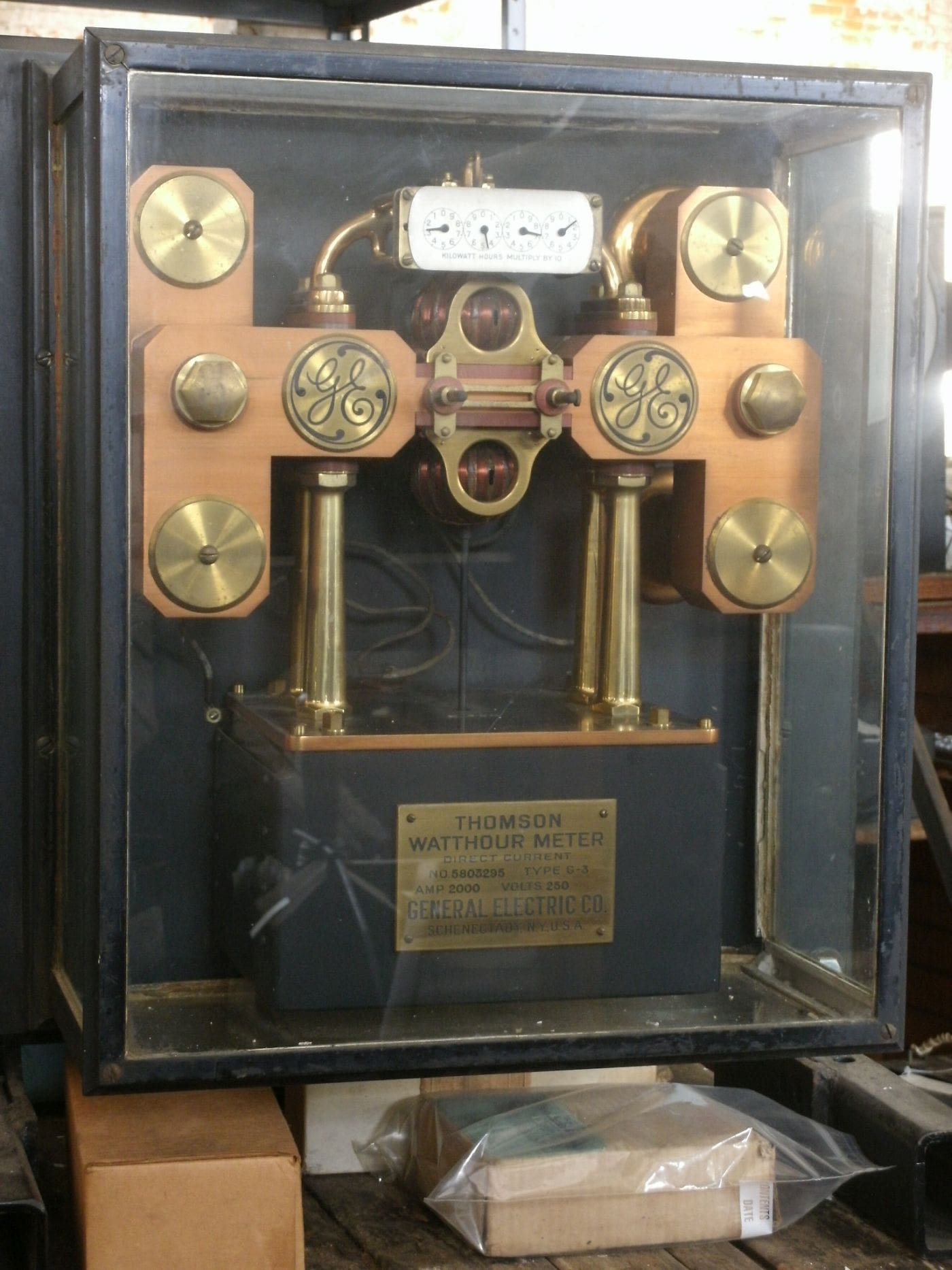
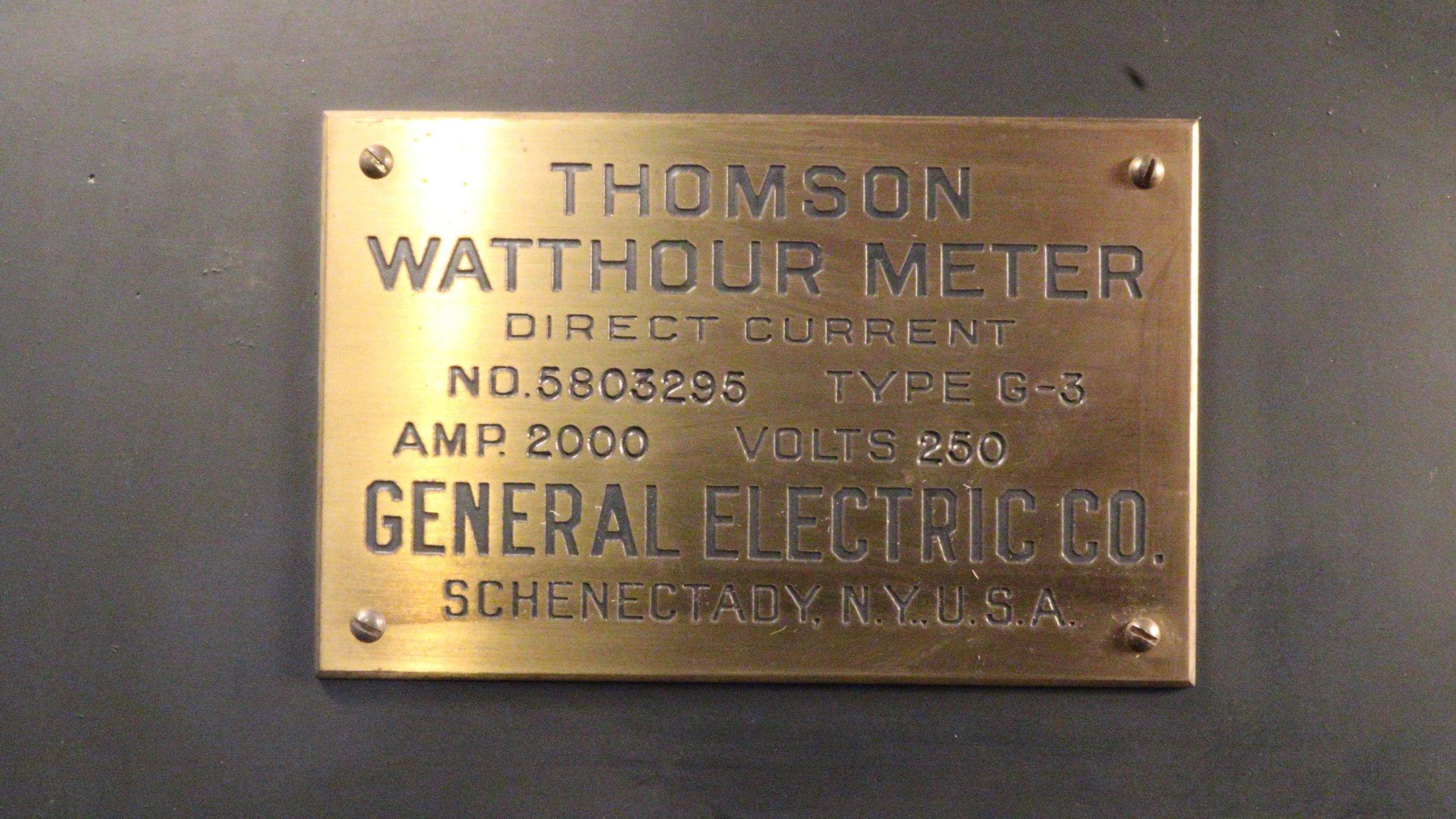
This watthour meter is a remarkable machine. There couldn’t have been many of these devices ever. In the left picture, it has its original protective boxy glass cover over it. The box is 19 ½ x 22 ½ inches. The major conductors are about 15 ½ wide, 10 inches high. And it’s heavy.From the nameplate we find that this had a maximum capacity of 2,000 amperes and 250 volts. Multiply the two, and that yields that the maximum is 500,000 (that’s half a million) watts!
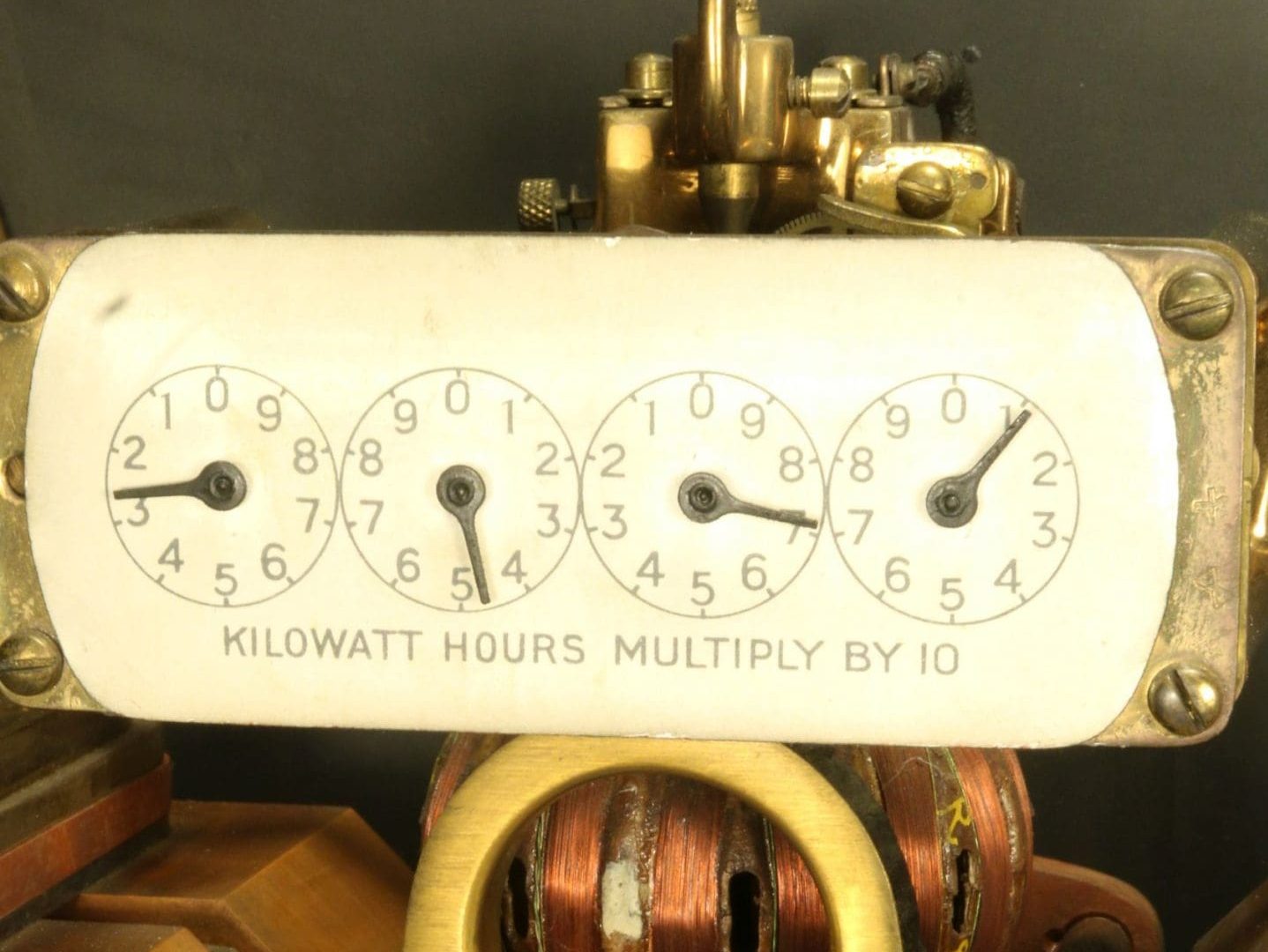
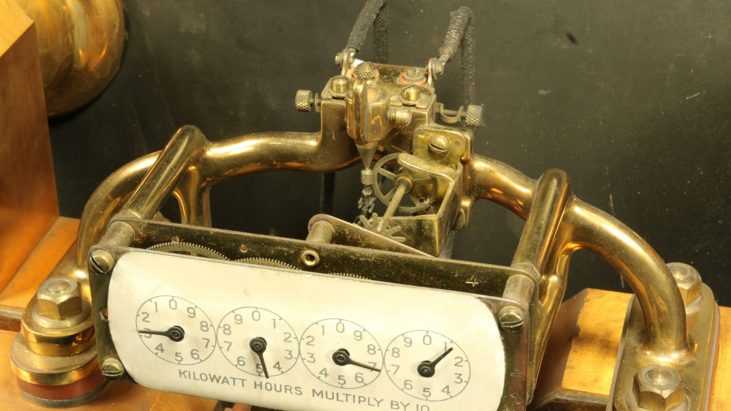
And there are those four dials at the top that look just like the ones I grew up with at home in the second half of the 20th century. (Granted, the rest of that machine was a lot smaller, not so pretty, and lived under a fishbowl.) The dials are mysterious in both the new and old devices in that two of the dials rotate clockwise, two counterclockwise. They were explained to my 7th grade Science class as being the minimal way to use gears. That is, the pair of gears on the back of one hand turns the gear pair on the back of the hand that it’s next to, and the result is that the neighbors turn in opposite directions.
Well, it seems there is a gage owner’s advantage in this. What I’m thinking is that the user of the electricity and the machine would need to figure out how the dials related to each other if they wanted to ask informed questions or complain to the electricity supplier. Most customers would find it too much bother or confusion to make the calculation.
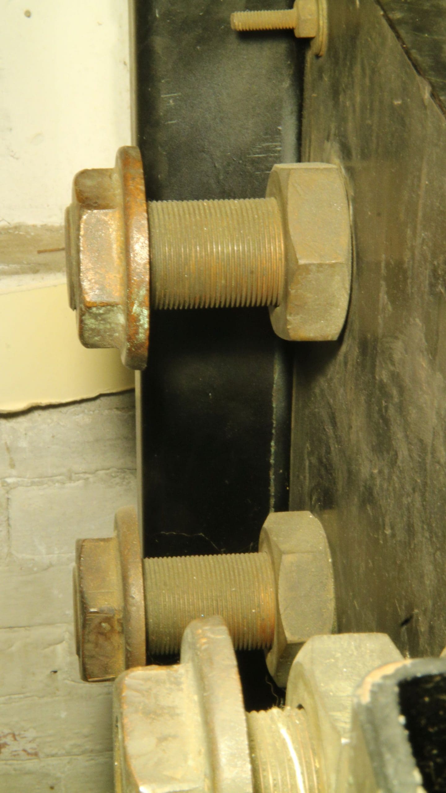
Maybe the most impressive thing about the gage is the scale of the parts that do the serious electrical conducting. The lugs on the back to connect to the outside electrical system have threads 1¾” in diameter. The blocks of copper inside are also very big so that they conduct with little resistance.
On the other hand, there are the parts that move the indicating hands. Those parts, in the middle, up at the very top of the mechanism, are quite similar in size to what you might find in a wind-up alarm clock. Not what you would call “imposing” at all. The small and large make a nice contrast. The mechanism is driven by the rotation of a vertical rod with two balls on it.The balls are made hollow out of ribbons that are made of thin copper wires grouped into bands which are carefully wrapped around a ball-form and glued there, perhaps with varnish.
The balls seem to be calibrated: the upper one’s marked 89, the other is R25.

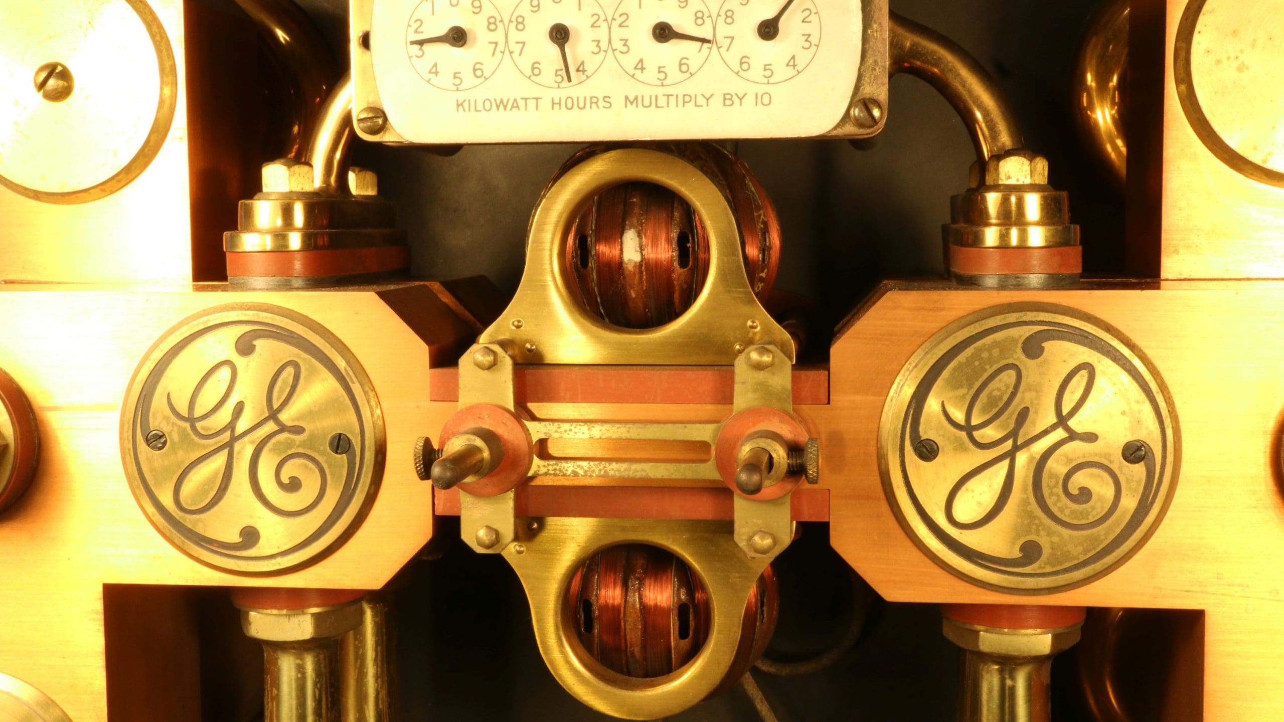 The upper ball has a separate, roughly rectangular, white mark, a dab of paint. I think it’s a way that someone looking at the device could watch the ball spin and easily infer, in a rough analog way, how active the electricity was at that time.
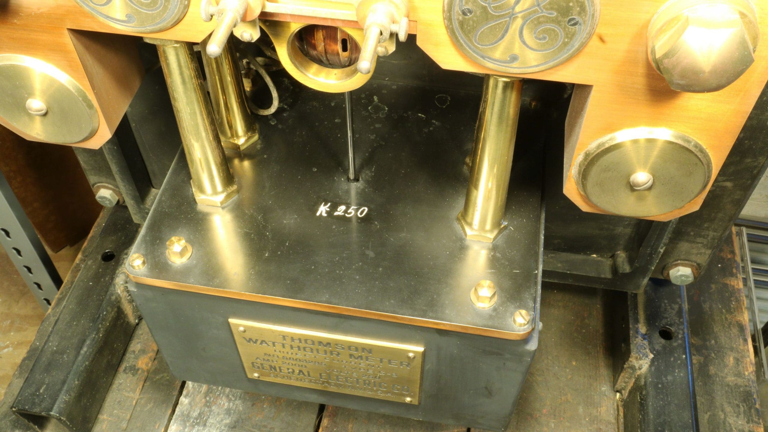 The black rod disappears into the near-cubical box at the bottom. I don’t know what might happen in there to make it rotate.
The whole meter unit is mounted on a piece of black slate (like what they used to make blackboards out of) that’s 1 ½ inches thick. The slate is used as a stiff, flat surface that is a good insulator as well as quite strong.
Various pieces of brass are held at a distance from other parts by terracotta red-colored insulating material, which is rubber.
The other striking thing about the machine is how beautiful it is. They went to a lot of trouble making a soft, neat finish on most of the metalwork. The copper comes to precise (that is, “not rounded”) corners. Most of it is varnished so there’s very little corrosion.
I mentioned (and pictured) four big studs that transmit the current in and out. We have two of the cables that connected to them. They are around 9 feet long overall. Wire like what these cables are made of (which is copper) couldn’t have been strung any distance between poles, as modern wires are, because they were too heavy and not very strong.
Modern high voltage cables move lots more electric energy through much smaller, less expensive, aluminum wires. These cables, that go from tower to tower, have a steel core that provides support so that they can carry their weight.
Perhaps the main advantage of AC is that it can be passed through a transformer to have its voltage changed up or down. It can travel great distances at a high voltage with low amperage and then be transformed down and be able to offer a higher amperage capacity.
Very few of those working in electricity around 1900 understood how the process worked as a modern engineer would understand it. Engineer and teacher Charles Steinmetz was the first to work out the math.
Just when was this device made? I’m depending on Wikipedia for the history. Rather than try to make a whole new article out of theirs, I’ve tried to extract a few things that seem relevant to our meter.
Edison just didn’t understand the advantages of alternating current. He seems to have really hated it. Much of the trouble that involved his companies swirled around this AC/DC issue. He lost majority control when a merger in 1889 formed Edison General Electric.
The various electric companies were involved in around 60 ongoing lawsuits, many of which were over patents. A committee of financiers arranged a behind the scenes deal that was announced on April 15, 1892. This put Thomson-Houston (Edison’s biggest competitor) in charge of the new company, called simply General Electric (no longer using Edison’s name). Edison, who only heard about the deal on the day before it was final, was greatly hurt.
Where there had been 15, now only two large electrical companies, GE and Westinghouse remained.
You will note that the nameplate is engraved, “Thomson,” and General Electric. There’s no mention of “Edison.” So certainly, it was made after April 15, 1892. But since there’s a tendency to “clean up” information that will be seen by others, it’s quite possible that the nameplate is not the original one, that the meter is older.
This seems especially likely to be true in a case like this where a “war” happened and DC was on the losing end.
Many more details of this conflict are in the Wikipedia article titled, “The War of the Currents” that I’ve been quoting here. The name refers to the conflict between the advocates of AC and DC.
stay up to date
Want more content from the American Precision Museum?
Sign up to receive news straight to your inbox!