Blog
Machine of the Month: Gilman 4-in-1 Part 2
By John Alexander, Collections Technician
Just can’t leave well enough alone!
Looking at the Gilman 4-in-1 machine (last month’s Tool of the Month), I realized I still needed to talk about its drive train. There’s a picture of the motor in the base of the machine, but we see no connections. The lack of electrical connections undoubtedly stems from the fact that the machine was restored to glory but not expected to work again. But mechanical connections are still there. As you’d expect, there’s a drive pulley on the other end of the motor.
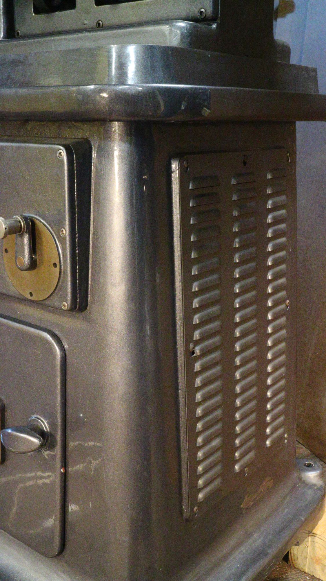
That area is accessed by removing a louvered panel on the right end of the machine. The motor has two drive belts. The belts on this machine are quite stout by modern standards, considering the very modest one-horsepower rating of the motor. (That’s right—only one horsepower from that big motor! I misreported the manufacturer’s tag in the last column.)
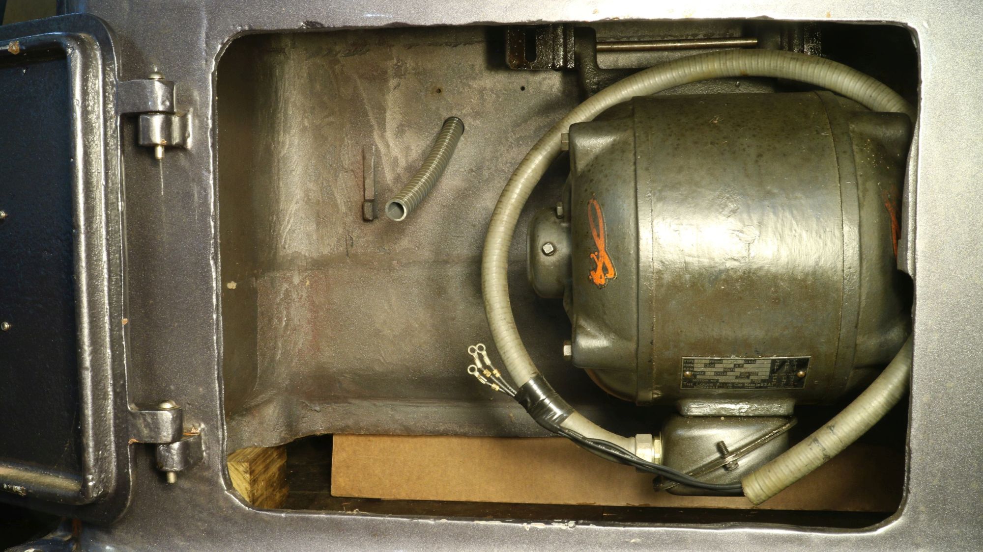
Two considerations might have led to the big belts: Rubber in that era probably wasn’t nearly as durable as the stuff that we have now. Also, the idea of a machine failing in wartime in a hostile ocean would have made the designing engineers very uncomfortable. I also got some perspective from the Museum’s own Joe Whelehan, who spent time at sea with the Navy. He told me that salt air has a destructive effect on rubber that naval personnel had to work every day to counteract.
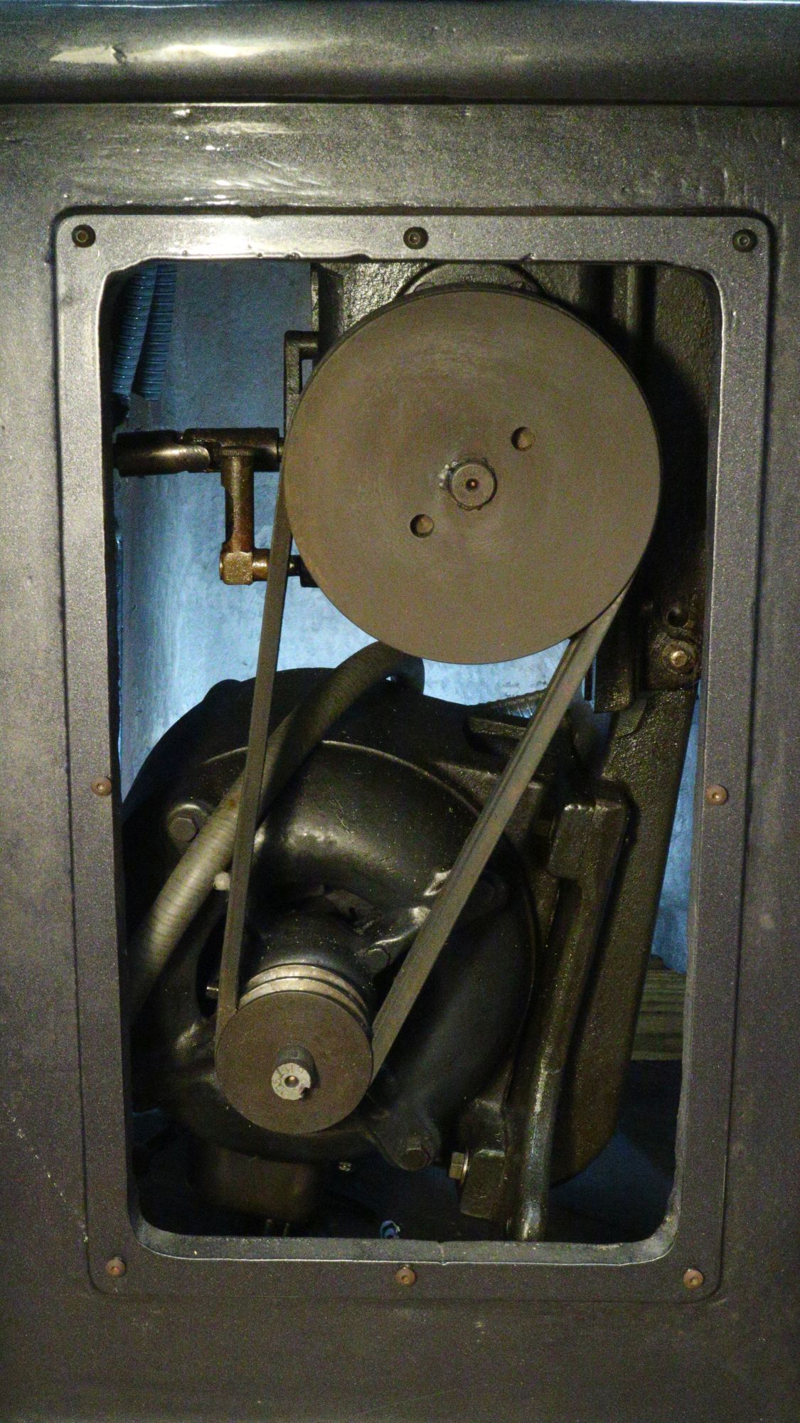
V-belts were relatively new when these machines were made, having come to market in 1917. The path of the power from the motor is through those two belts on the right side of the machine, and from there, it is through the transmission mounted on the ceiling of the motor cabinet (the cabinet being the base of the machine).
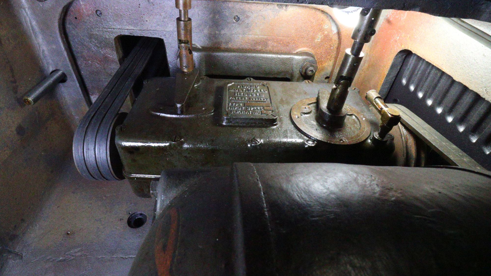
The big, rounded mass with the orange decal on it is the motor. On the right, you can just see the upper pulley with two belts. That’s the input side of the speed transmission. There is a sight glass to maintain the oil level in the transmission. It’s blocking most of the view of the upper pulley. The inside of the louvres is just to the right. The speed transmission itself has a plate with cast-raised letters on it.
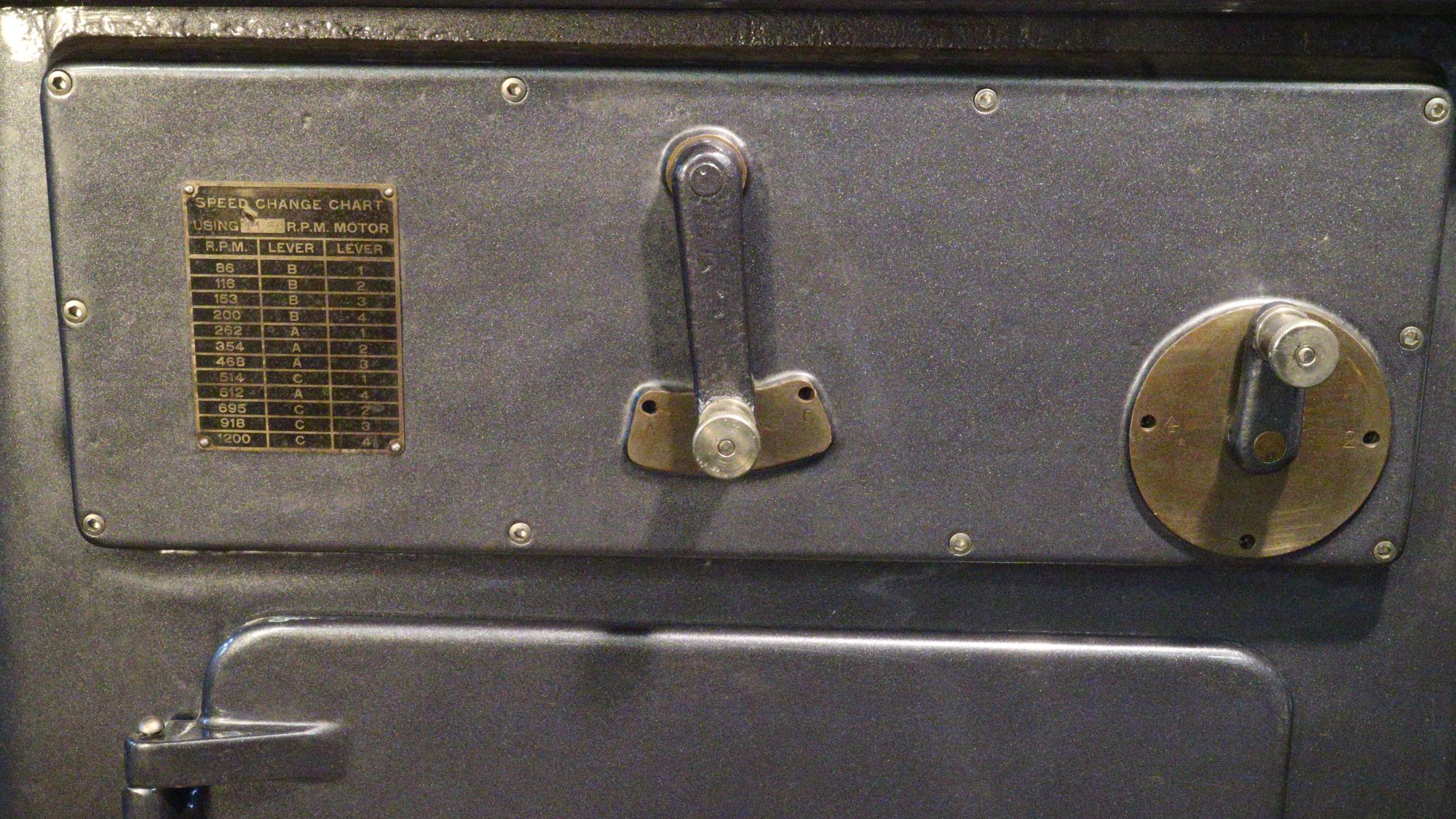
It offers different speeds to the pulley that drives the three belts on the left, which go from the output of the transmission up to the spindle that serves both the horizontal mill and the lathe. This transmission is controlled by the lower two handles on the front of the machine. To the left of the belts is the ¾” diameter threaded rod that lifts and lowers the knee of the milling table.
The round, gear-like part that drives or is driven by a silent chain is called a “sprocket.” Both chain and sprocket have gear-like teeth that engage each other. Apparently, they are much quieter than more common chain drives. The access panel just above the drill press table has a tag that says, “Remove Cover For Chain Tension Adjustment.” The tension is increased by pushing a roller against the outside of the chain.
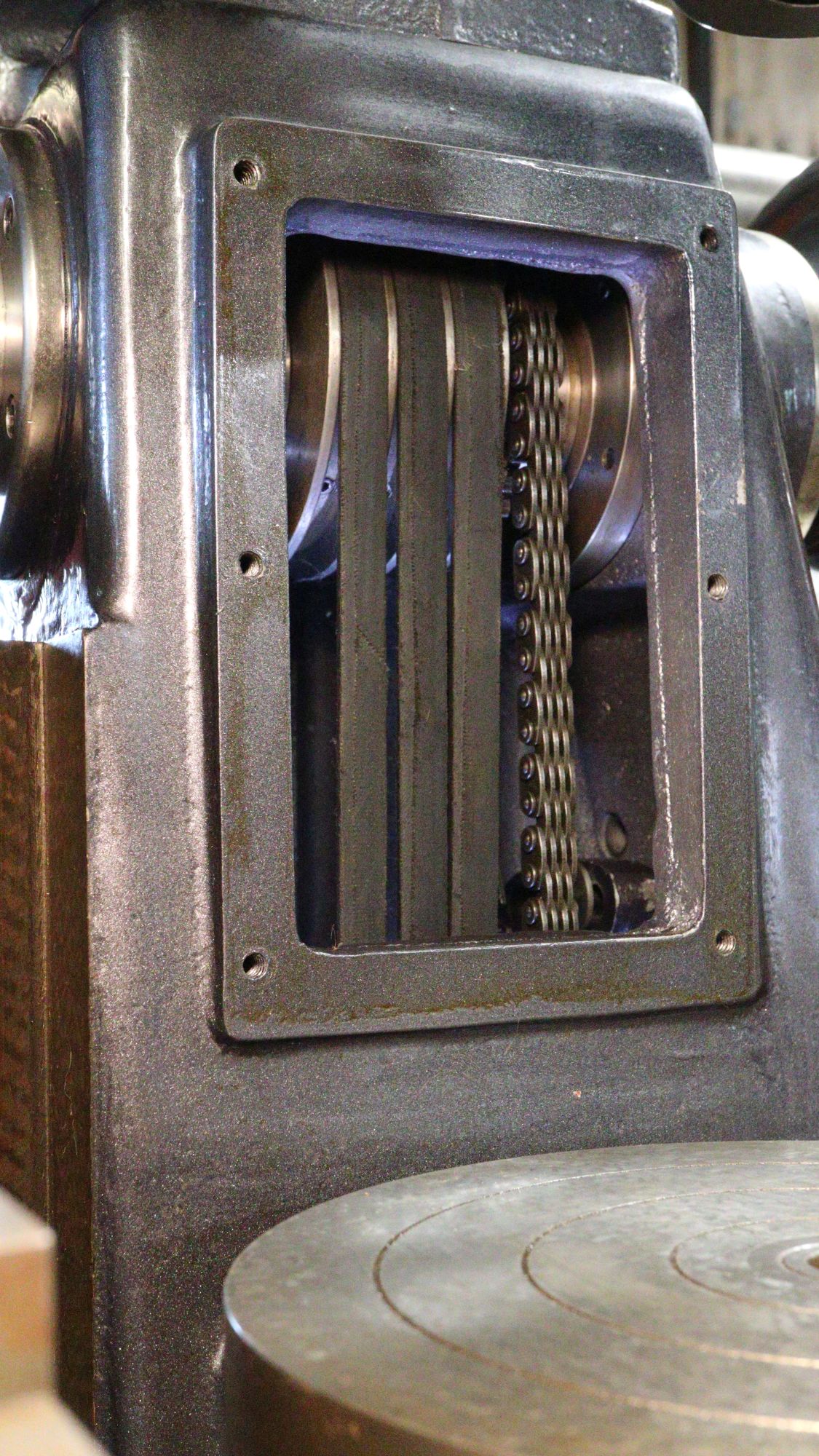
Since the outside of the chain is relatively smooth, the roller needs no teeth. If the roller acted on the toothed inside of the chain, it would need teeth matching the chain to interact smoothly. The upper two handles on the front of the machine control this second transmission that the chain feeds.
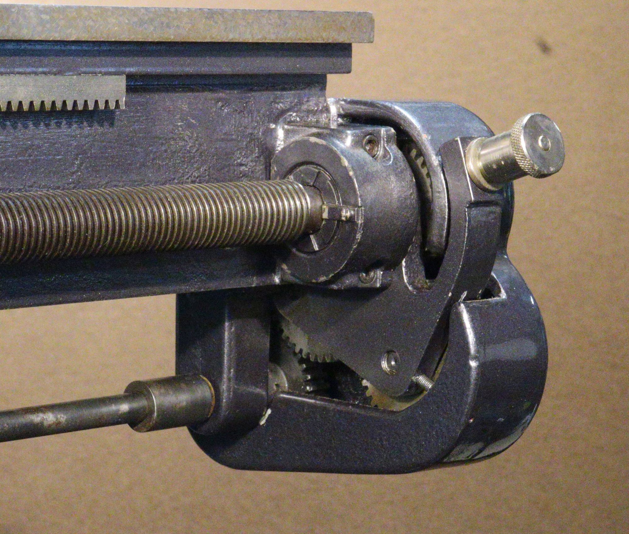
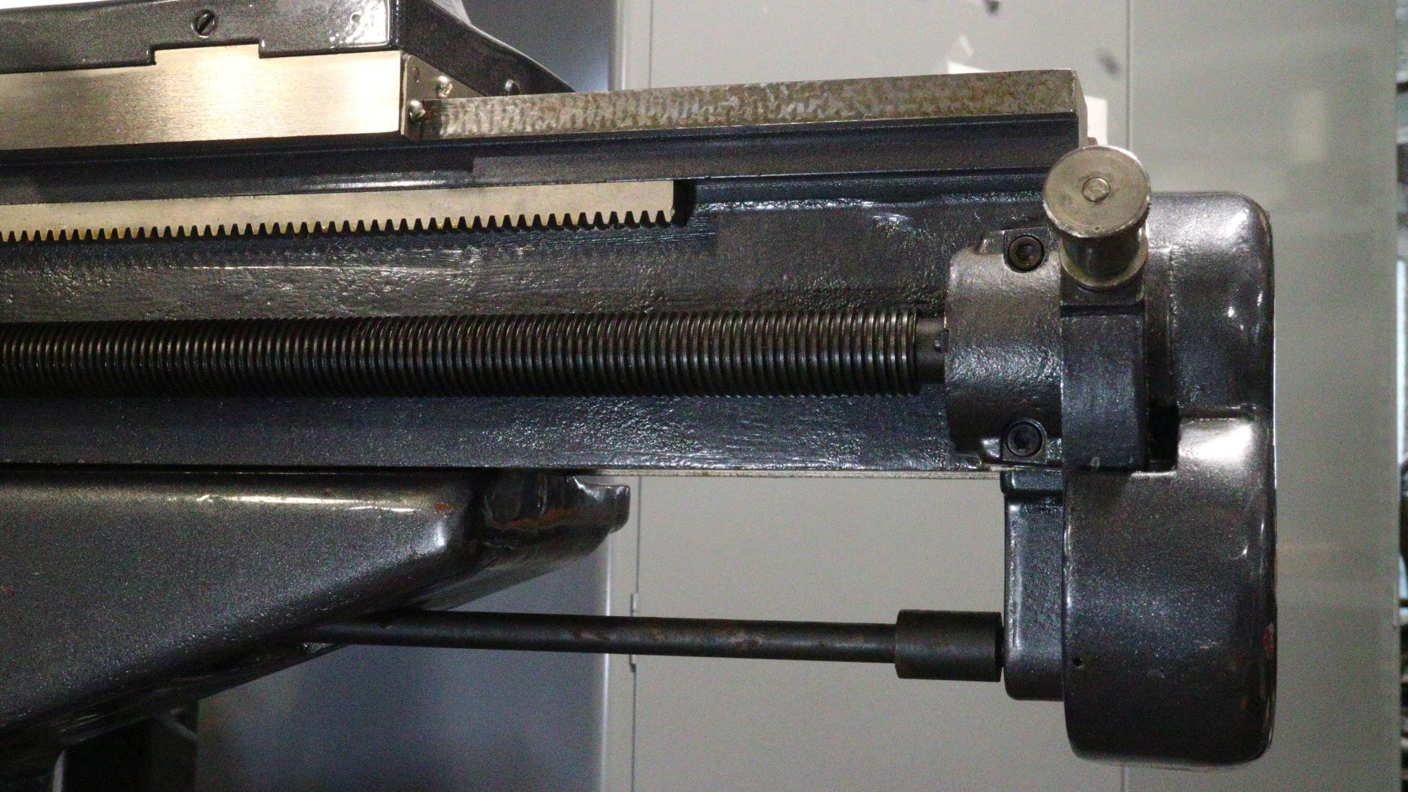
Power from this transmission moves the carriage left and right, giving the options of various feed rates and screw thread pitches.
The output from this transmission turns a rod below the ways that goes to a gearbox at the end of the ways. Using a knob on the front of the gearbox, the operator can reverse the cutting tool’s direction of feed. The knob will also engage or disengage the feed entirely. The power from the gearbox drives the large threaded rod, which moves the carriage. It’s the lead screw. (That’s pronounced to rhyme with “reed” rather than “red”.)
After all the time I’ve spent looking at this machine, I wonder about its history. While it probably never worked on a ship, did it work at all? What is original but “cleaned up a little,” and what is replaced or “radically restored?” The most apparent change from the original is the paint. That snazzy metal flake finish is far from Wartime Drab.
Well, whatever. A creation ahead of its time? The Gilman remains a well-designed and desirable machine after all these years.
stay up to date
Want more content from the American Precision Museum?
Sign up to receive news straight to your inbox!